Frame Scope
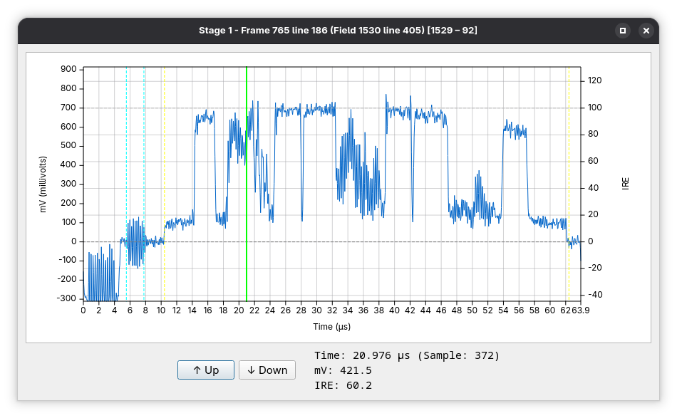
The Frame Scope is a line oscilloscope: it plots every sample of one video line of the frame on show in the Preview window. Like the Preview window it is not a pipeline stage, but a read-only view of the output of the stage currently being previewed, including the effect of every stage upstream of it.
It is the tool for sample-level signal analysis — sync, blanking and white levels, burst placement, noise, ringing and dropouts — at a precision the picture alone cannot give.
Renamed in v2.0: This dialogue was called the Line Scope in Decode-Orc 1.x.
Opening the Frame Scope
Click anywhere on the picture in the Preview window. The Frame Scope opens on the line under the pointer, and the preview draws cross-hairs at the point clicked. Holding the button down and dragging over the picture moves the scope from line to line as you go. When the previewed stage does not offer the view, the Preview window's status bar says Line scope is not available for this stage instead.
The scope follows the preview: stepping or playing to another frame redraws the same line of the new frame. Closing the scope removes the cross-hairs from the preview.
The window title names the stage, the frame and the line being shown (Stage N – Frame M, Line L …), with the line given in the selected numbering mode. Frame numbers are 1-based, as in the Preview window.
The plot
- The horizontal axis is time along the line, in microseconds.
- The vertical axis is signal level in the project's amplitude unit — IRE, millivolts or 10-bit samples — as chosen in File → New Project… or File → Edit Project…. The axis is not clamped to the nominal range: it reaches below sync tip and above peak white, and widens to take in any sample outside that range.
- Dashed reference lines mark the normative levels for the video system — Sync tip, Blanking, Black (when it differs from blanking, as on NTSC with set-up), White and Peak — taken from the video parameters in effect at the previewed stage, so a
video_paramsoverride moves them. - A vertical marker shows the selected sample. Click or drag on the plot to move it; the cross-hairs in the Preview window follow.
Beside the controls a read-out gives the time and sample number of the marker and the signal value there, in the project's amplitude unit (both values, Y and C, when a Y/C source is shown as Both).
Controls
| Control | Description |
|---|---|
| Channel | Y/C sources only: Luma (Y), Chroma (C), Both (Y & C) (the default, two traces) or Y+C (the two summed into a composite signal). Hidden for composite sources. |
| Line numbering | How the line is numbered in the title and read-outs (see below). |
| ↑ Up / ↓ Down | Step to the previous or next line without leaving the scope. Hold to repeat. |
Line numbering modes
| Mode | Description |
|---|---|
| Frame flat (0-based) | Line index within the stored frame, counted from 0 — the numbering the project file and the CLI use for frame lines. |
| Frame sequential (1-based) | The same lines counted from 1. |
| Field relative | Field number and the line's position within that field. |
| Broadcast interlaced | The standard broadcast line number (ITU-R BT.470-6 for 625-line systems, SMPTE 170M-2004 for 525-line systems). |
The mode is remembered between sessions. Changing it does not change which line is shown, only how it is labelled.
Typical uses
- Checking sync tip, blanking, black and white levels against the reference lines, before and after
video_params - Looking at the colour burst on the back porch, and at what a chroma-related stage did to it
- Examining dropout regions before correction, and the replacement data after
dropout_correct(itshighlight_correctionsparameter makes the corrected samples easy to find) - Seeing the flattened region left by
mask_line - Comparing noise before and after
stacker
For a view across every line of the frame use the Frame Timing View; for level distributions over many lines use the Waveform Monitor described in Preview.