JVC VIDEO TECHNICAL GUIDE VTG82063 - SECTION 7
AUDIO CIRCUIT
7.1 AUDIO TECHNOLOGY ADVANCES
Television sound multiplex broadcasts were not available at the time of the first home video tape recorders. As the VHS standard tape speed (NTSC: 33.35 mm/s. PAL/SECAM: 23.39 mm/s) is close to that of an audio cassette, single track recording with a fixed audio head was adequate for the era.
With the arrival of multiplex TV sound and marketing of video music prerecorded cassettes, the VHS normal audio track was subdivided into two stereo channels to allow VHS stereo recording and playback.
At about the same time, VTRs with extended mode capability began to appear. In this mode, the tape is transported at 1/3rd (NTSC: 11.12 mm/s) or 1/2 (PAL/SECAM: 11.7 mm/s) the standard mode. This capability was accompanied by increased demand for further improved picture and sound quality.
The VHS Hi-Fi was thus developed in order to meet these demands. The system overcomes the limitations of fixed audio heads and the slow transport speed by using rotating audio heads.
Models that include the VHS Hi-Fi feature also retain the fixed head recording capability. Thus these models possess two recording systems, one for fixed head "normal" recording, and the other a stereo system for rotating head FM recording. These models also allow receiving a TV signal while recording an external audio signal.
7.1.1 Sound recording systems
Two audio recording and playback systems are used in presently marketed VHS products. One is recording the audio and bias signals directly onto the tape by a fixed head. The other is by rotating audio heads that insert the sound in FM form into the video signal band.
1. Fixed head recording
This is the original and most basic magnetic recording method. The audio signal is recorded together with AC bias of at least twice the highest audio frequency (typically 3 to 5 times). AC bias recording features good linearity and naturalness, plus low non-linear distortion.
Generally speaking, sound quality in the fixed head recording system is proportional to the tape speed. The width of the recording track also affects S/N (tape noise). A tape speed of 9.5 cm/s is needed to adequately record the audible frequency range (20 Hz to 20 kHz) with the fixed head system.
The VHS tape speed is 33.3 mm/s and home VTR tape is equivalent to the chrome position of audio cassette tape. However, as the tape speed slows, the playback output at higher frequencies diminishes rapidly. Thus, standard mode VHS is capable of about 10 kHz, but in the extended mode, this drops to about 8 kHz.
With the advent of TV sound multiplex broadcasts, the VHS normal audio track was further divided to accommodate two stereo tracks. Moreover, this reduced the track width of each channel to about 0.3 mm, and inadequacy at high frequency and loss of S/N were unavoidable.
Noise reduction was added in order to improve S/N especially at high frequencies. The circuit functions by compressing the signal during recording, then expanding it upon playback. The Dolby B noise reduction system was incorporated into VHS models for reducing tape hiss and improving performance at high frequencies.
2. Rotary head recording (VHS Hi-Fi)
The VHS Hi-Fi system was developed in response to demand for improved audio quality in the extended mode. In this system, the audio signal is frequency modulated at approximately 1.5 MHz and recorded on the tape by rotating heads.
During playback, filter circuits yield the FM audio signal. This is demodulated to reproduce the sound.
The FM recording system maintains high S/N with respect to playback output level fluctuations. Another advantage is comparatively simple circuit composition.
The audio carrier is inserted between the down converted color and FM luminance signals. Deep layer recording is used for insertion. VHS Hi-Fi models are capable of two channel recording and playback.
While this system is capable of high quality audio recording, since the same tape area is used for both video and Hi-Fi audio signals, subsequent audio dubbing is disallowed. This poses no problem in recording TV broadcasts and playing commercially recorded tapes. However there is a disadvantage in editing live video recordings. The fixed head normal recording facility is therefore retained in Hi-Fi models to permit audio dubbing in these cases.
7.2 DESCRIPTION OF VHS Hi-Fi TECHNOLOGY
7.2.1 VHS Hi-Fi D-MPX (Depth-Multiplex) recording system : NTSC
In the VHS Hi-Fi system, the video and audio heads are independent of each other. First the audio signal is recorded and then the video signal is recorded on top of the audio signal. Because of this method, the frequency band of the video signal is never affected by the audio signal and full VHS compatibility is maintained. This is a definite advantage over other Hi-Fi video systems. Generally, the recorded wavelength is determined by \(\lambda = V/F\).
- \(\lambda\) : Wavelength
- \(V\) : Relative tape speed 5.8 m/sec
- \(F\) : Frequency
For an FM video signal of 4.4 MHz, the wave-length on the tape is approximately 1.3 \(\mu\)m. For the carrier frequency of 3.4 MHz, the wavelength is approximately 1.7 \(\mu\)m.
As illustrated, the recorded wavelength of the video signal ranges from about 1.3 to 1.7 \(\mu\)m is recorded to a depth of about 0.3 \(\mu\)m on the magnetic coating of the tape by the 0.3 \(\mu\) gap of the video head.
In contrast of this, the FM audio signal for Hi-Fi recording and reproduction has a carrier frequency of 1.3 MHz for channel 1 and 1.7 MHz for channel 2. Converted into the recorded wavelength, they are about 4 \(\mu\)m for channel 1 and about 3.4 \(\mu\)m for channel 2.
When the video and FM audio signals are recorded on the same track of the tape, the audio signal magnetizes the tape far deeper than the video signal, as illustrated, and a portion on the deep layer remains even after the video signal is recorded on the surface layer. This means both signals remain with no interference to each other.
The frequency spectrum (see Fig. 7-2-1) of the recorded signals shows that the FM audio signal frequency band lies between Y and C. However, because the audio signal is recorded independently of the video signal, no side band of the Y and C signals is sacrificed. These signals have exactly the same frequency spectrum as in the conventional VHS system.
To sum up, the VHS Hi-Fi system employs a recording method that does not introduce any degradation of the video signal due to the FM audio signal. The azimuth angle of the audio head is \(30^{\circ}\), far greater than the \(6^{\circ}\) azimuth angle of the video head. The \(30^{\circ}\) azimuth was established to provide a sufficient azimuth effect on the audio signals, which have longer wavelengths.
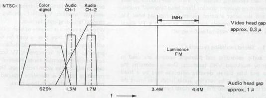
Fig. 7-2-1 VHS Hi-Fi recording spectrum (NTSC)
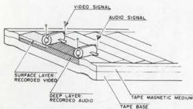
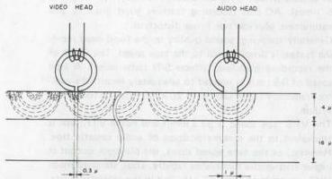
Fig. 7-2-2 VHS Hi-Fi recording system
7.2.2 Crosstalk rejection by azimuth difference: NTSC
In VHS Hi-Fi, the video heads have an azimuth angle of \(+6^{\circ}\) and \(-6^{\circ}\); and the audio heads, \(+30^{\circ}\) and \(-30^{\circ}\). Because of this difference, crosstalk between audio and video signals and that between audio signals on adjacent tracks are all effectively suppressed. The situations shown here clearly demonstrate that the VHS Hi-Fi system achieves crosstalk rejection sufficient to superbly reproduce audio and video signals. Even in the EP mode which is more susceptible to crosstalk, only a slight degree of crosstalk is detected as indicated by these graphs.
Lines (A) are plotted for output level (EP mode) obtained when the azimuth of the head coincides with that of the magnetic pattern as a function of the overlapping track-width. Output level is expressed in percentage (100% for a track of 19 microns fully overlapped by the head gap). The lower groups of curves (B) represent the output of crosstalk components of audio signals. The head azimuth difference in each situation is shown at the upper right corner of the graph.
Fig. 7-2-4(A) shows crosstalk between adjacent audio tracks. A rejection of more than \(20\mathrm{dB}\) is observed with audio signals when the overlapping track width is 19 microns. Fig. 7-2-4(B) shows crosstalk between audio and video signals on the same track, and Fig. 7-2-4(C) crosstalk between the video signal and the audio signal on adjacent tracks.
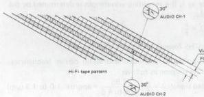
Fig. 7-2-3 VHS Hi-Fi magnetic tape pattern
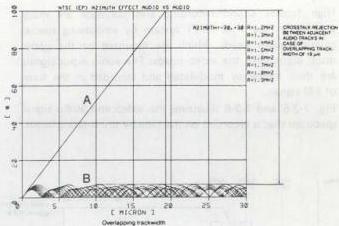
Fig. 7-2-4(A) Crosstalk between adjacent audio tracks
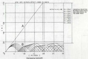
Fig. 7-2-4(B) Crosstalk between audio and video
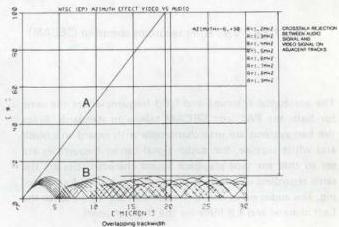
Fig. 7-2-4(C) Crosstalk between audio and adjacent video
7.2.3 VHS Hi-Fi outline : PAL/SECAM
High fidelity sound recording and playback are made possible in the VHS Hi-Fi system by employing special rotating audio heads, which are mounted on the upper drum along with the video heads. The audio input signals are then frequency modulated and recorded in the form of FM signals.
Fig. 7-2-5 and 7-2-6 illustrate the video and audio signal spectrum that is recorded on the tape by the rotating heads.
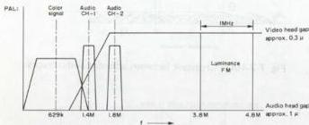
Fig. 7-2-5 VHS Hi-Fi recording spectrum (PAL)
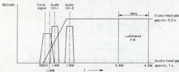
Fig. 7-2-6 VHS Hi-Fi recording spectrum (SECAM)
The horizontal scanning and field frequencies are the same for both the PAL and SECAM television standards. Since the two systems are interchangeable with regard to a black and white picture, the audio signal carrier frequencies are set so that the tape playback sound characteristics are the same regardless of which of these systems is used for recording. The audio signal carrier frequencies are 1.4 MHz for the Left channel and 1.8 MHz for the Right channel.
By using the special Hi-Fi rotating audio heads, since the frequency deviation is large (±50 kHz at operating level and ±150 kHz maximum) the signal to noise and dynamic range characteristics are fully adequate for high fidelity applications. Also, even though the audio signal is inserted between the color and luminance signals, since it is recorded independently of the video information, there is no need to change the video signal spectrum, while audio signal effects on picture quality are nearly absent.
When a magnetic head records a signal on a tape that has already been recorded, the previous signal is not erased. Instead, both signals become overlapped. Also, if the recording wavelength is short, while the azimuths of the recording and playback heads differ, the playback output is strongly attenuated.
These effects are employed by the VHS Hi-Fi system. The video and audio signals are each recorded by heads with different azimuth angles and are overlapped on the tape. The azimuth difference then exerts a separating effect during playback.
7.2.4 VHS Hi-Fi D-MPX recording system: PAL/SECAM
In the VHS Hi-Fi system, the audio signal is first recorded on the video track by special rotating heads, then the video signal is recorded over this by the video heads. Since the recording wavelength of the audio signal is longer than that of the video signal, it is recorded deeply in the magnetic layer of the tape.
With the recording speed taken as \(\nu\), and the recording frequency as \(f\), the recording wavelength is determined by the formula:
In the VHS format, this is: \(\nu = 4.85\) (m/sec)
When applied to the video and audio carrier frequencies, the values become as follows.
Video signal: \(\lambda = \frac{\nu}{f} = \frac{4.85}{3.8 \text{ to } 4.8} = \text{approx. } 1.0 \text{ to } 1.3\) (μm)
Audio signal: \(\lambda = \frac{\nu}{f} = \frac{4.85}{1.4 \text{ to } 1.8} = \text{approx. } 2.7 \text{ to } 3.5\) (μm)
Recording in the tape thickness direction introduces thickness loss which attenuates the playback output to a certain degree. Also, the optimum playback sensitivity is obtained when recording is performed at a depth equivalent to 1/4th the recording wavelength. In considering these factors, the optimum recording depth \(d\) becomes as indicated below.
Video signal: \(d = \frac{\lambda}{4} = \frac{1.0 \text{ to } 1.3}{4} = \text{approx. } 0.26 \text{ to } 0.36\) (μm)
Audio signal: \(d = \frac{\lambda}{4} = \frac{2.7 \text{ to } 3.5}{4} = \text{approx. } 0.68 \text{ to } 0.89\) (μm)
As indicated in Fig. 7-2-7, when these signals are recorded on the same tape, the audio signal is recorded in the deep portion of the magnetic layer, while the subsequently recorded video signal occupies the portion toward the tape surface.
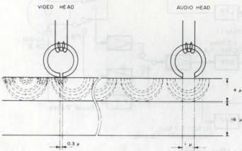
Fig. 7-2-7 VHS Hi-Fi recording system
When the surface portion is erased by the video signal in this manner, separation loss attenuates the audio signal playback output level. As can be noted from the following calculation, if \(0.3\mu \mathrm{m}\) of the surface portion is erased, the attenuation becomes 5.3 dB.
Attenuation = 54.6 d/λ (dB)
d: Head to recorded portion distance
\(\lambda\): Audio signal recording wavelength (example is \(3.1 \mu \mathrm{m}\))
In actual measurement, the attenuation exceeds 5.3 dB. However, the remaining amount is fully adequate for the purposes of retaining audio signal quality and performance. Signal separation upon playback is performed by using different azimuth angles for the video and audio heads. Azimuth loss (used to advantage in this system) occurs when the azimuth angles of the recording and playback head differ. This loss also increases and decreases according to the signal frequency.
Consequently, separation is performed by using azimuth angles of \(\pm 30^{\circ}\) for the audio heads and \(\pm 6^{\circ}\) for the video heads.
7.3 FM AUDIO CIRCUIT PRINCIPLE
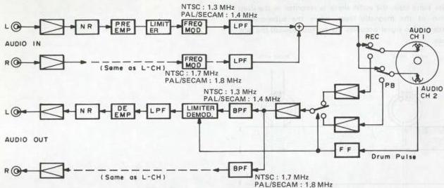
Fig. 7-3-1 FM audio block diagram
7.3.1 FM audio recording signal flow
1. VHS Hi-Fi noise reduction
Since the VHS Hi-Fi system uses frequency modulation (FM), triangular noise occurs during demodulation. Although emphasis reduces this noise, the effectiveness is not fully adequate. Consequently, the noise reduction circuit combines low frequency emphasis with logarithmic compression of the audio input signal.
Fig. 7-3-2 shows a block diagram of the noise reduction. The compression circuit functions to raise low level audio input signals, but reduce high level signals. This is followed by a weighting circuit which serves to avoid excessive high frequency emphasis during recording. A peak level detection system is used.
Emphasis Time Constant T1 = 240 µs, T2 = 56 µs Weighting Time Constant T1 = 240 µs, T2 = 24 µs Attack Time 3 to 10 ms Recovery Time 70 ms
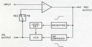
Fig. 7-3-2 VHS Hi-Fi noise reduction block
2. Pre-emphasis
The purpose of the pre-emphasis circuit is to maintain S/N at high frequencies. In FM systems, demodulation noise increases linearly as the frequency increases. During playback, S/N can be improved by reducing the gain of only the pre-emphasized component. The pre-emphasis time constant is set for 56 µs.
3. Input limiter
The FM audio signal frequency band expands with increased input signal level. In order to prevent affecting the video signal, the input signal is limited to a fixed maximum.
4. Frequency modulator
[NTSC]
The frequency produced by the frequency modulator varies linearly with the input signal level. Center carrier frequencies are 1.3 MHz ± 10 kHz for the Left (Main) channel and 1.7 MHz ± 10 kHz for the Right (Sub) channel. Frequency deviation is ±50 kHz, with maximum set at ±150 kHz.
[PAL/SECAM]
The frequency produced by the frequency modulator varies linearity with the input signal level. Center carrier frequencies are 1.4 MHz ± 10 kHz for the Left (Main) channel and 1.8 MHz ± 10 kHz for the Right (Sub) channel. Frequency deviation is ±50 kHz, with maximum set at ±150 kHz.
5. Lowpass filter (LPF)
The FM signal from the modulator has a nearly square waveform and includes harmonics which would interfere with the video signal if recorded. The LPF yields a nearly sine waveform that eliminates these harmonics.
6. Recording amplifier and recording level
The FM signal is amplified to a level sufficient for recording on tape (approximately 2.2 Vp-p). The recording level adjustment is important, since excess level may interfere with the video signal, while audio S/N may be impaired if the level is too low.
7.3.2 FM audio playback signal flow
1. Preamplifiers, Channel switcher and FM AGC
The playback signals from the rotary audio heads are sent through the rotary transformers, then preamplified approximately 60 dB and supplied to the channel switcher. This uses the drum flipflop signal to produce continuous signals. The FM AGC circuit serves to compensate for level fluctuations due to variations in head to tape contact.
2. Bandpass filter (BPF)
[NTSC]
The left channel BPF passes the \(1.3\mathrm{MHz} \pm 150\mathrm{kHz}\) FM signal and the right channel BPF passes the \(1.7\mathrm{MHz} \pm 150\mathrm{kHz}\) FM signal.
[PAL/SECAM]
The left channel BPF passes the \(1.4\mathrm{MHz} \pm 150\mathrm{kHz}\) FM signal and the right channel BPF passes the \(1.8\mathrm{MHz} \pm 150\mathrm{kHz}\) FM signal.
3. Playback limiter, Frequency demodulator and LPF
The playback limiter removes AM components from the playback FM signal. Phase locked loop (PLL) demodulation is performed using the same demodulator circuit (VCO) used in recording. The LPF removes FM carrier components from the demodulated audio signal.
4. Switching noise reduction
1) Head switching noise
When the FM audio signals are recorded and played back by the rotary audio heads, pulse type noise is generated by the head switching process. Also, carrier phase disturbance occurs in the overlap portion due to slight differences in tape tension and other factors between recording and playback.
As indicated in Fig. 7-3-3, the instantaneous phase of the carrier changes at the head switching point. This results in a frequency deviation change that appears as pulse type noise in the demodulated signal.
In the case of the video signal, head switching is performed outside the picture region. However, since blanking is absent from the audio signal, processing is required in order to remove the noise.
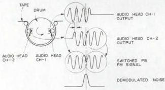
Fig. 7-3-3 Head switching noise
2) Pre-hold method
This technique uses a sampling and hold circuit as shown in Fig. 7-3-4. Demodulated audio signal (a), which includes pulse noise, is sampled by hold pulse (b) produced from the head switching signal. The result is held to prevent transfer of the noise to the following stage.
The width of hold pulse (b) is generally set for about \(20\mu\mathrm{s}\) in order to adequately cover the pulse noise which has been affected by the bandpass filter for the FM signal and the lowpass filter for cutting high frequency noise after demodulation.
This method is comparatively simple and effective at removing pulse noise. However, it does not perform well at high frequencies.
Interpolation error is indicated in waveform (c) of Fig. 7-3-4. Even though operation is nearly ideal at no signal and at low frequency, additional error is produced with respect to high frequency and high slew rate signals.
In actual music signals, high frequencies tend to possess lower level than midrange. The music also tends to mask the noise produced by interpolation error to where it is not easily detected. However, in the case of sounds approaching a mono-frequency, the noise cannot be ignored.
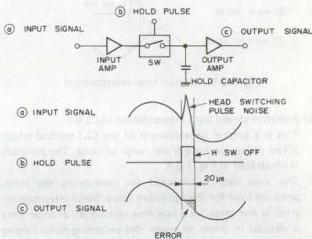
Fig. 7-3-4 Pre-hold method
3) Reduced interpolation time
There are two techniques for improving the performance of the pre-hold method. One of these is to shorten the interpolation time.
This consists of designing for appropriate response in the bandpass filter for the FM signal and lowpass filter for the demodulated signal. If the pulse noise is prevented from widening, the minimum required hold pulse can be used.
By this relatively modest improvement, interpolation time can be reduced to less than half and interpolation error reduced considerably.
4) Closed loop interpolation (CLI)
In addition to shortening the interpolation time, this technique can further reduce interpolation error. This principle is illustrated in Fig. 7-3-5.
The slope just prior to the noise component is detected and the holding capacitor is discharged accordingly. The slope data are applied to a loop for performing interpolation.
Compared with the pre-hold method, this system offers greater interpolation error suppression without regard to frequency.
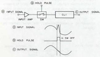
Fig. 7-3-5 Closed loop interpolation
5) Adaptive closed loop interpolation (ACLI)
This is a further development of the CLI method which offers reduction for a wider range of noise. The principle is illustrated in Fig. 7-3-6.
The slew rate is detected for controlling the interpolation time for the optimum value. Since interpolation error is not large for a low slew rate signal, a longer time is desired in order to cover the switching noise ringing component. However, a shorter interpolation time provides better overall noise reduction for a high slew rate signal.
Fig. 7-3-7 illustrates the noise spectrum for \(15\mathrm{kHz}\) recording and playback. The pre-hold method is shown by waveform A, CLI by B and ACLI by C.
In the case of C, switching noise is eliminated and system noise (tape noise, etc.) becomes dominant in the waveform.
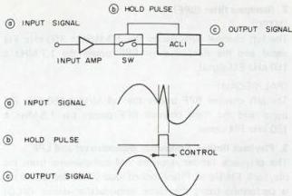
Fig. 7-3-6 Adaptive closed loop interpolation
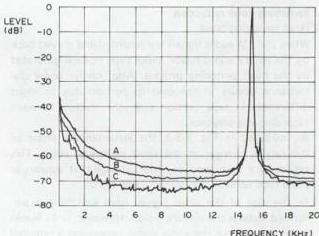
Fig. 7-3-7 Noise spectrum
6) Advanced new tangent system
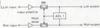
The advanced new tangent system is the improved version of the previous new tangent system, and correction can be made for both Lch and Rch.
See Fig. 7-3-8.
In the new tangent system, correction is performed by averaging the value of the correction period of the switching noise of Lch and Rch. In this case, the noise of Lch is larger than the noise of Rch, when the signals of Lch and Rch are different. The reverse is also true.
In the advanced new tangent system, correction operation is properly controlled according to the rate of each channel. This improves the noise component due to the switching noise.
 (New tangent system)
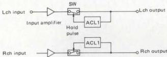
Fig. 7-3-8
(Advanced new tangent system)