JVC VIDEO TECHNICAL GUIDE VTG82063 - SECTION 1
VHS BASICS TECHNOLOGY
1.1 VHS FORMAT DESCRIPTION
1.1.1 VHS outline
The Video Home System (VHS) format was conceived as a means to bring video tape recording within the reach of the average consumer. Since its development, advances in all aspects of the technology, including greater video head provision and improved video tape, have yielded a wide variety of functions and features. Versions are also available for the world's major television systems, NTSC, PAL and SECAM.
VHS resulted from meeting several technical challenges for improving picture quality and resolution. Signal to noise ratio, crosstalk and over modulation were among the many problems encountered and resolved. The techniques for overcoming these difficulties include slant azimuth recording system, non-linear emphasis, double limiter and phase shift circuit designs.
1. VHS Hi-Fi system
In terms of sound and picture quality, the initial series of VHS video cassette recorders was fully adequate for general purpose household entertainment. However, a market was also recognized among those who owned or planned to purchase high quality stereo audio systems.
The VHS Hi-Fi system was therefore developed for enhanced audio performance along with outstanding picture quality. Special rotating audio heads increase the relative tape to head speed to 5.80 m/sec (NTSC) / 4.85 m/sec (PAL/SECAM), thereby providing true high fidelity frequency response in the audio range of from 20 Hz to 20,000 Hz, as well as a dynamic range exceeding 90 dB.
The audio signal is frequency modulated at 1.3 MHz (NTSC) / 1.4 MHz (PAL/SECAM) for the left channel and 1.7 MHz (NTSC) / 1.8 MHz (PAL/SECAM) for the right channel. Maximum deviation is ±150 kHz.
Recording is performed by a “depth multiplex” (D-MPX) system, whereby both sound and picture are recorded on the same portion of the tape. The audio signal is recorded at a deeper level than the video, while the azimuth angles of the audio and video heads differ sufficiently to prevent cross-interference.
2. HQ (high quality)
Advances in circuit technology and in television receivers provided impetus to further improve the picture quality of VHS equipment. This led to the HQ (high quality) series which incorporates the following technical features.
1) Increased white clip level 2) Detail enhancer 3) Luminance noise reduction (YNR) 4) Chrominance noise reduction (CNR)
Increasing the white clip level improves the picture edge sharpness. The detail enhancer functions by increasing the level of the high frequency low amplitude component of the signal, which is often lost in the REC/PB process. More detailed pictures are then obtained during playback.
YNR reduces noise at the picture edges and flat portions, while CNR contributes to reducing color smear.
HQ technology offers overall picture improvement and increases the recording and playback quality of home video recorders.
3. S-VHS objectives
The trend in color television receivers is continuing toward larger screens and high picture quality. Nearly all of these new generation TV sets are connected to home video cassette recorders.
Demand is thus increasing for evermore detailed and realistic video reproduction. The S-VHS Euro system was developed to meet this goal and provide picture quality that approaches a 1-inch professional video tape recorder at a cost accessible to the consumer.
4. S-VHS features
1) Horizontal resolution exceeds 400 lines. This is fully adequate to accommodate presently broadcast problems (about 330 lines) without degradation in picture quality. 2) Vivid realistic reproduction gives video program artists more freedom of expression and promotes higher quality software availability. Since more than 400 lines are also obtained in the EP/LP mode, software for this mode may appear in the near future. 3) Color video cameras and VideoMovie systems compatible with S-VHS are becoming available. Self-made video programs will be able to reval broadcast television quality. 4) The high picture quality and economical cost of S-VHS enables a broad range of commercial uses, such as video publishing, travel guides, sales manuals, etc.
1.1.2 VHS and S-VHS compatibility
1. Equipment
S-VHS video recorders have two selectable operating modes for recording and playback: S-VHS and VHS.
2. Modes
Cassettes recorded in the S-VHS mode must be played back also in the S-VHS mode. If played back in the VHS mode (or with a VHS-only deck), a usable picture is not obtained.
1) An S-VHS recorded cassette cannot be played on a VHS-only deck. 2) A VHS recorded cassette may be played on an S-VHS deck.
3. Cassette
1) For best results in the S-VHS mode, use an S-VHS cassette. (An ordinary VHS cassette will not deliver full performance in this mode.) 2) An S-VHS cassette may also be used in the VHS mode (or with a VHS-only deck).
Fig. 1-1-1 illustrates the compatibility between cassette types and video recorder modes.
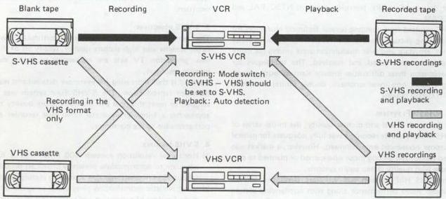
Fig. 1-1-1 VHS/S-VHS compatibility
4. Super VHS and European color system compatibility
Tapes recorded in Super VHS anywhere except NTSC areas can be played back on any Super VHS Euro system deck.
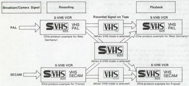
Fig. 1-1-2 S-VHS Euro system and European color system
1.1.3 Magnetic tape pattern
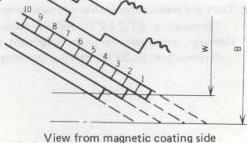
Fig. 1-1-3 shows the recorded tape pattern for the VHS/S-VHS format with longitudinal (fixed head) audio tracks. This is the basic pattern without the rotary audio head feature. The VHS/S-VHS Hi-Fi tape pattern is produced by first laying down the pattern shown in Fig. 1-1-4 at nearly saturation level. Afterwards, the VHS/S-VHS format video and audio pattern of Fig. 1-1-3 is recorded over this to yield the D-MPX (Depth Multiplex) pattern used for the VHS/S-VHS Hi-Fi system.
1. Slant azimuth principle
Due to the physical properties affecting magnetic tape and heads, maximum signal output is obtained when the azimuth angle of a playback head precisely matches that of the recording head (and tape track). As the difference between these angles increases, the playback output drops sharply.
In the standard VHS/S-VHS format, two rotary video heads are mounted at \(\pm 6\) degrees azimuth relative to each other. The resulting video tracks become a chevron-like pattern as illustrated in Fig. 1-1-3. During playback, since each head yields an effective output only when it traces its corresponding track, crosstalk between video tracks is reduced to a level where it can be corrected by techniques described below.
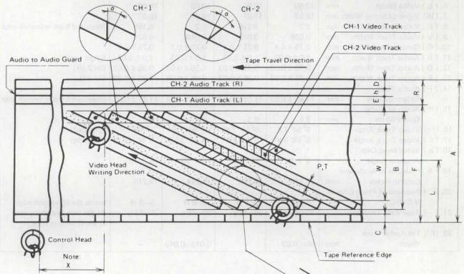
Fig. 1-1-3 VHS/S-VHS magnetic tape pattern
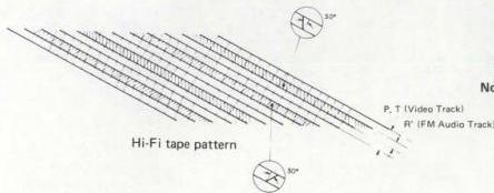
Fig. 1-1-4 VHS/S-VHS Hi-Fi magnetic tape pattern
 View from magnetic coating side
Note: Distance from the CH-2 video track 180° outlet point to CTL signal pulse.
The same principle as this is also employed for the sound information in the VHS/S-VHS Hi-Fi system. In this case, the rotary audio heads are mounted at \(\pm 30\) degrees azimuth angles. Consequently, the tape pattern is characterized by four helical tracks at four different azimuth angles.
View from magnetic coating side
Note: Distance from the CH-2 video track 180° outlet point to CTL signal pulse.
The same principle as this is also employed for the sound information in the VHS/S-VHS Hi-Fi system. In this case, the rotary audio heads are mounted at \(\pm 30\) degrees azimuth angles. Consequently, the tape pattern is characterized by four helical tracks at four different azimuth angles.
Table 1-1-1 lists the main specifications of the magnetic tape pattern.
| Item | NTSC | PAL/SECAM | Remarks | ||
|---|---|---|---|---|---|
| SP mode | EP mode | SP mode | LP mode | ||
| 1. (A) Tape Width mm | 12.65 ± 0.01 | 12.65 ± 0.01 | 12.65 ± 0.01 | 12.65 ± 0.01 | |
| 2. (Vt) Tape Speed mm/sec | 33.35 ± 0.5% | 11.12 ± 0.5% | 23.39 ± 0.5% | 11.70 ± 0.5% | |
| 3. (φ) Drum Diameter mm | 62 ± 0.01 | 62 ± 0.01 | 62 ± 0.01 | 62 ± 0.01 | (Upper Drum) |
| 4. (Vh) Writing Speed m/sec | 5.80 | 5.83 | 4.85 | 4.86 | |
| 5. (P) Video Track Pitch mm | 0.058 | 0.019 | 0.049 | 0.024 | |
| 6. (B) Video Width mm | 10.60 | 10.60 | 10.60 | 10.60 | |
| 7. (W) Video Effective Width mm | 10.07 | 10.07 | 10.07 | 10.07 | |
| 8. (L) Video Track Center mm | 6.2 | 6.195 | 6.2 | 6.195 | Measured from reference edge |
| 9. (V) Video Track Width mm | 0.058 | 0.019 | 0.049 | 0.024 | |
| 10. (C) Control Track Width mm | 0.75 ± 0.1 | 0.75 ± 0.1 | 0.75 ± 0.1 | 0.75 ± 0.1 | |
| 11. (R) Audio Track Width mm | 1.0 ± 0.03 | 1.0 ± 0.03 | 1.0 ± 0.03 | 1.0 ± 0.03 | Single track |
| 12. (D) Audio Track Width mm | 0.35 ± 0.03 | 0.35 ± 0.03 | 0.35 ± 0.03 | 0.35 ± 0.03 | CH-2 (R) |
| 13. (E) Audio Track Width mm | 0.35 ± 0.03 | 0.35 ± 0.03 | 0.35 ± 0.03 | 0.35 ± 0.03 | CH-1 (L) |
| 14. (F) Audio Track Reference Line mm | 11.65 ± 0.03 | 11.65 ± 0.03 | 11.65 ± 0.03 | 11.65 ± 0.03 | Measured from reference edge |
| 15. (h) Audio to Audio Guard Width mm | 0.3 | 0.3 | 0.3 | 0.3 | |
| 16. (θo) Video Track Angle | 5° 56' 7.4" | 5° 56' 7.4" | 5° 56' 7.4" | 5° 56' 7.4" | (Stopped) |
| 17. (θ) Video Track Angle | 5° 58' 9.9" | 5° 56' 48.1" | 5° 57' 50.3" | 5° 56' 58.8" | (Running) |
| 18. (α) Video Head Gap Azimuth Angle | 6° ± 10' | 6° ± 10' | 6° ± 10' | 6° ± 10' | |
| 19. (X) Positions of Audio and Control Heads mm | 79.244 | 79.253 | 79.244 | 79.248 | |
| 20. ( ) Positions of Front Edge of V-SYNC | 5-8 H | 5-8 H | 5-8 H | 5-8 H | Inside the W bottom edge |
| 21. ( ) Tape Back Tension | 30-45 g | 30-45 g | 30-45 g | 30-45 g | At the tape beginning and at the drum entrance |
| 22. (R') FM Audio Track Width mm | Min. 0.02 | - | 0.016-0.049 | - |
Table 1-1-1 Magnetic tape pattern
Note: Tests and measurements shall be made under the following conditions.
Temperature: \(20^{\circ}\mathrm{C} \pm 2^{\circ}\mathrm{C}\), Relative humidity: \(65\% \pm 5\%\)
However, unless essential to the judgement, these can also be done under the following conditions.
Temperature: \(5-35^{\circ}\mathrm{C}\), Relative humidity: \(40-80\%\)
2. Horizontal correlation (NTSC)
Horizontal (H) correlation is one of the techniques employed for reducing the effects of residual adjacent channel crosstalk. In this system, the writing start of one television scanning line is delayed 1.5 H (the time equivalent to 1.5 horizontal TV scanning lines) with respect to the previous scanning line.
The slant azimuth recording system is capable of eliminating most channel crosstalk at high frequencies. However, for the low frequency component, where the VHS/S-VHS color information is situated, this system is less effective.
Since the visual information between two adjacent television scanning lines differs only slightly, by employing horizontal correlation, demodulated color crosstalk components become aligned with the main information of neighboring lines. Consequently, the visual disturbance due to residual crosstalk is minimized.
An additional advantage of horizontal correlation is evident during special operating modes, such as slow motion, still frame and search. In these modes, even though the video heads trace more than one recorded track, the horizontal sync signals are played back at fixed intervals, thereby minimizing visual disturbance.
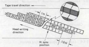
Fig. 1-1-5(A) VHS/S-VHS recording signal pattern (NTSC)
3. Horizontal correlation (PAL/SECAM)
The azimuth head configuration removes crosstalk from most of the high frequency portion of the FM luminance signal, however, it is not able to fully eliminate crosstalk from the low frequency component of the lower side-band portion. This residual crosstalk is reduced by employing line correlation for the tape pattern.
Line correlation (or "H correlation") consists of arranging the horizontal sync signal positions of adjacent recorded tracks. Since this makes the frequencies of the main signal and crosstalk signal very close, the demodulated crosstalk amount becomes extremely low with respect to the main signal. The type of H correlation used in the VHS/S-VHS format is shown in Fig. 1-1-5(B).
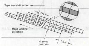
Fig. 1-1-5(B) VHS/S-VHS recording signal pattern (PAL/SECAM)
1.1.4 VHS luminance signal recording system
Frequency modulation (FM) is used for the luminance signal recording system. A simplified block diagram of the system is shown in Fig. 1-1-6.
A lowpass filter (LPF) removes the color component and passes only the luminance component of the input color TV signal. At the next stage, the pre-emphasis circuit, the high frequency portion of the luminance signal is enhanced in order to improve the S/N ratio during FM recording.
Since excess pre-emphasis could lead to black/white reversal due to the shortened recording wavelength, a white/dark clip circuit cuts the overshoot and under-shoot components which exceed certain positive and negative levels.
The frequency modulator (FM MOD) converts the AM luminance signal to FM, which goes through a highpass filter (HPF) to the recording amplifier. These circuits amplify the signal with the proper frequency characteristic, after which it is mixed with the down-converted color signal and supplied to the video heads.

Fig. 1-1-6 Luminance signal recording system
1. Luminance signal recording frequency characteristic
As shown in Fig. 1-1-7, when the video input is a color TV signal, a lowpass filter removes the color component.
This leaves the luminance signal, with a bandwidth from about \(30\mathrm{Hz}\) to \(3.0\mathrm{MHz}\). With some VHS models, when the input is a black and white TV signal, it by-passes the LPF; allowing a wider bandwidth to beyond \(4.5\mathrm{MHz}\) (NTSC) or \(4\mathrm{MHz}\) (PAL/SECAM).
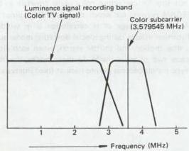
Fig. 1-1-7(A) Luminance signal recording band (NTSC)
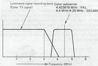
Fig. 1-1-7(B) Luminance signal recording band (PAL/SECAM)
2. Pre-emphasis characteristics
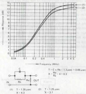
Fig. 1-1-8 Pre-emphasis characteristics
3. White and dark clip level
White clip level and dark clip level are as shown in Fig. 1-1-9.
Note: The level from sync tip to white peak is 100%.
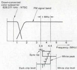
Fig. 1-1-9(A) Recording spectrum (NTSC)
4. FM carrier frequency and deviation
See Fig. 1-1-9.
| NTSC | Sync tip : 3.4 ± 0.1 MHz |
|---|---|
| White peak : 4.4 ± 0.1 MHz | |
| Deviation : 1.0 ± 0.1 MHz | |
| PAL/SECAM | Sync tip : 3.8 ± 0.1 MHz |
| White peak : 4.8 ± 0.1 MHz | |
| Deviation : 1.0 ± 0.1 MHz |
5. FM signal recording frequency
As indicated in Fig. 1-1-9(A)/(B), when the video input is a color TV signal, it goes through an HPF, clearing an area for the down-converted color signal. With some VHS models, when the input is a B/W TV signal, the HPF can be bypassed to extend the bandwidth to the DC area.
6. FM signal recording amp. current (REC amp)
Current:
| More than 3.8 MHz | : Optimum saturation recording current |
|---|---|
| 2 MHz | : 3 ± 1 dB |
| 1 MHz | : 6 ± 1 dB |
| Less than 1 MHz | : Flat characteristics |
Note: 0 dB at 3.8 MHz
7. FM signal head current (video head)
Specified to be within ±1.5 dB of 4 MHz optimum recording current.
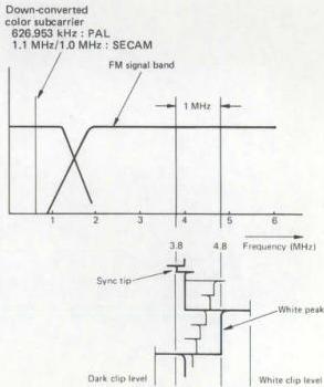
Fig. 1-1-9(B) Recording spectrum (PAL/SECAM)
1.1.5 VHS luminance signal playback system
This system functions to return the signals recorded on the tape to a form as close as possible to the video input signals. The simplified block diagram is shown in Fig. 1-1-10. The low level FM signals played back by the video heads are combined into a single FM signal by the switching amplifier. After amplification to the required frequency characteristic, a highpass filter attenuates the down-converted color signal and passes only the FM luminance signal. This HPF has the same response as that of the recording system.
Variations in the playback FM signal level due to mechanical stretching and contraction of the tape, and irregularities in tape to head contact, are corrected by the limiter circuit. The signal is amplified more than 80 dB to permit precise demodulation. A double limiter circuit is employed in order to prevent black/white reversal effects.
In the following stages, the demodulator and lowpass filter return the luminance signal to its AM form. The de-emphasis circuit reverses the emphasis applied during recording. From this point, the signal goes to the mixer where it is mixed with the playback color signal to become the video output signal.

Fig. 1-1-10 Luminance signal playback system
1.1.6 VHS color signal recording system (NTSC)
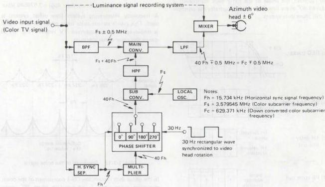
Fig. 1-1-11 Color signal recording system
This is a direct recording system using a down converted phase shifted color signal. The phase shift system removes color crosstalk which cannot be completely eliminated by the azimuth video heads. Fig. 1-1-11 illustrates a simplified block diagram of this system.
A bandpass filter (BPF) extracts the color component from the input video signal and supplies it to the main converter. At the same time, the input signal also goes to the horizontal sync separator, which supplies the \(15.734\mathrm{kHz}\) (Fh) to the multiplier and phase shift circuits. Via the phase shifter, the 40 Fh CH-1 track component is advanced in phase each line (1 H) and supplied to the sub converter, while the CH-2 component is delayed in phase \(90^{\circ}\) every line (1 H). A 30 Hz rectangular wave synchronized to the video head rotation is used for differentiating between the CH-1 and CH-2 components. Each line is also controlled by the Fh input.
The local oscillator produces the color subcarrier frequency of 3.579545 MHz (Fs). At the sub converter, the 40 Fh and Fs are frequency-converted to become \((Fs + 40 Fh)\). This is supplied through a highpass filter to the main converter. Also supplied to the main converter are the color signal \(Fs \pm 0.5 MHz\) and carrier wave \((Fs + 40 Fh)\). These are down-converted to become \((40 Fh \mp 0.5 MHz)\), which goes through a lowpass filter and then to the mixer for mixing with the FM luminance signal. The result is applied to the video heads.
In other words, the 3.579545 MHz (Fc) color subcarrier is converted to a low band of 629.371 kHz (40 Fh). The down converted color signal is then recorded directly, using the FM luminance signal as AC bias.
1. Color crosstalk correction by phase shift system
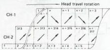
While the CH-1 track component is advanced \(90^{\circ}\) every line and recorded, the phase of the CH-2 track component is delayed \(90^{\circ}\) every line. Fig. 1-1-12 illustrates the principle of this phase shift system.
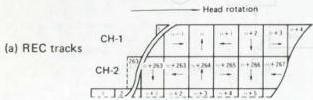
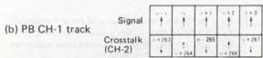
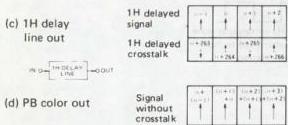
Fig. 1-1-12 Phase shift system
In the figure, (a) indicates the phase shifted recording pattern. The CH-1 head pattern phase is advanced \(90^{\circ}\) every line. The phase of the CH-2 head pattern is delayed every line.
During playback, when the CH-1 head picks up a portion of the CH-2 track signal, this becomes the crosstalk component. The main signal is delayed \(90^{\circ}\) every line from the CH-1 track, and this output is shown by (b). The dotted arrows indicate the crosstalk component and, as can be noted, the phase reverses every line.
Passing signal (b) through a 1 H delay line yields signal (c). In comparing signals (b) and (c), the main signal phase is the same every line, but the crosstalk phase reverses. Therefore, by mixing signals (b) and (c), the crosstalk component of the adjacent track can be removed to result in the playback color signal (d).
In other words, the signal is recorded by the phase shift system, and during playback it is mixed with the signal through a 1 H delay line to remove crosstalk.
Crosstalk in the playback color signal (d) effectively becomes zero, while the main signal is enhanced to improve the S/N ratio. Also, the CH-2 head playback phase is advanced \(90^{\circ}\) every line (opposite to recording), producing the same effect. A digital type system is used for phase shifting.
2. Down-converted color subcarrier frequency
The color subcarrier frequency (Fs) can be expressed as:
A frequency interleaving system (line offset system) is used. This avoids serious color noise when the color signal is displayed on a monochrome TV receiver. Fig. 1-1-13 shows this color signal spectrum.
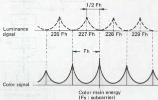
Fig. 1-1-13 Spectrum of the color signal
In the phase shift system, the CH-1 component of the down converted color signal is advanced in phase \(90^{\circ}\) every line, deviated by plus 1/4 Fh, and distributed at 1/2 Fh intervals centered on the Fc (down converted color subcarrier) component. The CH-2 track component is delayed in phase \(90^{\circ}\) every line, deviated by minus 1/4 Fh, and distributed at 1/2 Fh intervals centered on Fc. This spectrum is shown in Fig. 1-1-14.
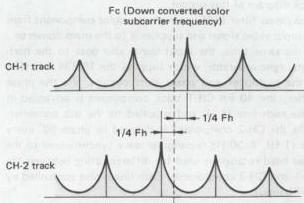
Fig. 1-1-14 Spectrum of down-converted color signal
The FM luminance and down converted color signals are mixed to become the recording current. When recorded and played back using magnetic tape, which possesses 3-dimensional distortion and nonlinearity, interference in the form of \(F_{D} + 2F_{DC}\) (Fo : FM carrier; Fdc : down converted color signal) is introduced and cannot be ignored. When the 2F dc component is detected and demodulated, a beat is produced with respect to the luminance signal and appears in the picture. Therefore, as with the color signal, Fc (down converted color subcarrier frequency) must be selected so that the frequency of the 2Fdc component becomes interleaved (1/2 offset) in relation to the luminance signal.
When Fc is determined at 40 Fh, the 2 Fdc spectrum of the CH-1 track component appears at (+1/2 Fh) and in the CH-2 track distribution, the 2 Fdc spectrum appears at (nFh - Fh).
Fig. 1-1-15 shows the 2 FDC component spectrum with respect to the playback luminance signal at this time.
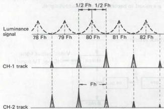
Fig. 1-1-15 2 FDC playback spectrum
The 2 Fdc components for both CH-1 and CH-2 become interleaved (1/2 line offset) with respect to the luminance signal and thereby visually reduced. The 629.371 kHz value was selected for both reducing noise and in consideration of color bandwidth.
3. Color signal recording bandwidth
Response curves for the bandpass and lowpass filters are indicated in Fig. 1-1-16.
Constant current characteristics are possessed by the down-converted color signal recording current.
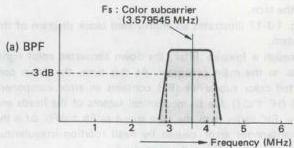
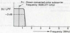
Fig. 1-1-16 Color signal recording bandwidth
1.1.7 VHS color signal playback system (NTSC)
The color signal playback system performs essentially the opposite function of the recording system. In addition, however, important corrections must be performed for color signal frequency and phase errors introduced by variations in tape speed and head rotation, and elasticity of the tape.
Fig. 1-1-17 illustrates an abbreviated block diagram of this system.
Through a lowpass filter, the down converted color signal goes to the main converter. At this time, the down converted color subcarrier (Fc) contains an error component \((40\mathrm{fH}^{\prime}\pm \Delta \mathrm{f})\) due to mechanical factors of the heads and tape. Fh' varies with the tape speed as Fh ± ΔFh. Δf is the instantaneous error caused by head rotation irregularities and tape elongation and contraction.
The 40 Fh' frequency deviation component is compensated by supplying the video output signal to the horizontal sync separator, multiplier and phase shifter, and 40 Fh' to the sub converter. This forms the AFC (automatic frequency compensator) loop.
In the APC (automatic phase compensator) loop, the \(\pm \Delta f\) phase error component is compensated by comparing the burst component of the up converted playback color signal with the subcarrier frequency from the local oscillator and APC detector. A variable crystal oscillator (VXO) produces \((\mathrm{Fs} \pm \Delta f)\) which goes to the sub converter. As a result, \((\mathrm{Fs} + 40 \mathrm{Fh}' \pm \Delta f)\) is supplied from the sub converter through a highpass filter to the main converter.
By frequency conversion with Fc, the color subcarrier frequency of 3.579545 MHz, which is free from frequency and phase deviations, is obtained through a bandpass filter. In the opposite manner, as with recording, the phase shifter delays the CH-1 track phase \(90^{\circ}\) every line, advances the CH-2 track phase \(90^{\circ}\) every line and 40 Fh' is supplied to the sub converter. The playback color signal through the main converter and bandpass filter is applied to a 1 H delay line to remove crosstalk. Characteristics of the lowpass and bandpass filters are the same as those for recording (Fig. 1-1-16).
At the mixer, the playback color and luminance signals are mixed to become the video output signal.
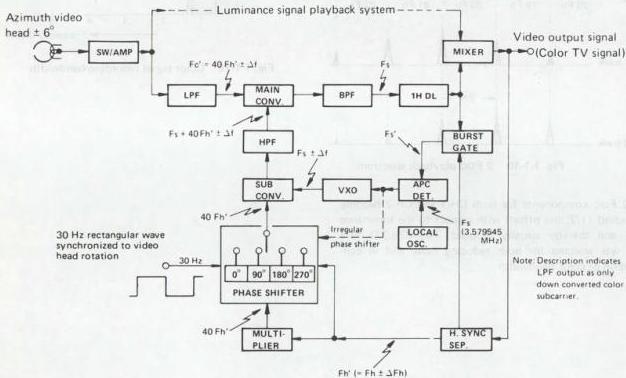
Fig. 1-1-17 Color signal playback system
1.1.8 VHS color signal recording system (PAL)
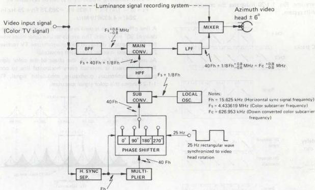
Fig. 1-1-18 Color signal recording system
This is a direct recording system using a down converted phase shifted color signal. The phase shift system removes color crosstalk which cannot be completely eliminated by the azimuth video heads. Fig. 1-1-18 illustrates a simplified block diagram of this system.
A bandpass filter (BPF) extracts the color component from the input video signal and supplies it to the main converter. At the same time, the input signal also goes to the horizontal sync separator, which supplies the 15.625 kHz (Fh) to the multiplier and phase shift circuits. Via the phase shifter, the 40 Fh CH-1 track component is supplied directly to the sub converter, but the CH-2 component is delayed in phase 90° every line (1 H). A 25 Hz rectangular wave synchronized to the video head rotation is used for differentiating between the CH-1 and CH-2 components. Each line is also controlled by the Fh input.
The local oscillator produces the color subcarrier frequency 4.433619 MHz (Fs) + 1/8 Fh single frequency which goes to the sub converter. At the sub converter, the 40 Fh and (Fs + 1/8 Fh) are frequency converted to become (Fs + 40 Fh + 1/8 Fh). This is supplied through a highpass filter to the main converter. Also supplied to the main converter are the color signal Fs +0.6 MHz and carrier wave (Fs + 40 Fh +1/8 Fh). These are down converted to become (40 Fh + 1/8 Fh +0.8 MHz) which through a lowpass filter goes to the mixer for mixing with the FM luminance signal. The result is applied to the video heads.
In other words, the 4.433619 MHz (Fc) color subcarrier is converted to a low band of 626.953 kHz (40 Fh + 1/8 Fh). The down converted color signal is then recorded directly using the FM luminance signal as AC bias.
1. Color crosstalk correction by phase shift system
A synchronous quadrature modulation system is employed in which the phase of the color signal R-Y component is reversed every line in order to prevent transmission distortion.
The color signal indicated in Fig. 1-1-19 is converted to a lowband.
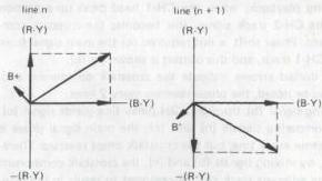
Fig. 1-1-19 Vector of color signal
While the CH-1 track component is recorded with phase unchanged, the phase of the CH-2 track component is delayed 90° every line. Fig. 1-1-20 illustrates the principle of this phase shift system.
(a) REC tracks
(b) PB CH-1 track
(c) 2H delay line out
(d) PB color out
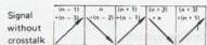
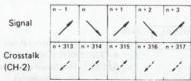
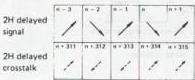
In the figure, (a) indicates the phase shifted recording pattern. Since the CH-1 head pattern is not phase shifted, the R-Y component phase becomes inverted every line. The phase of the CH-2 head pattern is delayed every line and this causes its R-Y component phase to become inverted every two lines.
During playback, when the CH-1 head picks up a portion of the CH-2 track signal, this becomes the crosstalk component. Phase shift is not required for the main signal from the CH-1 track, and this output is shown by (b).
The dotted arrows indicate the crosstalk component and, as can be noted, the phase reverses every 2 lines.
Passing signal (b) through a 2H delay line yields signal (c). In comparing signals (b) and (c), the main signal phase is the same every line, but the crosstalk phase reverses. Therefore, by mixing signals (b) and (c), the crosstalk component of the adjacent track can be removed to result in the playback color signal (d).
In other words, the color signal can be considered in 2 H units. It is recorded by the phase shift system and during playback, the signal through a 2 H delay line is mixed to remove crosstalk.
Crosstalk in the playback color signal (d) effectively becomes zero, while the main signal is enhanced to improve S/N. Also, the CH-2 head playback phase is advanced 90° every line (opposite to recording), producing the same effect. A digital type system is used for phase shifting.
2. Down-converted color subcarrier frequency
The color subcarrier frequency (Fs) can be expressed as:
A line offset system is used in which the subcarrier phase is delayed 90° every line. This avoids serious color noise when the color signal is displayed on a monochrome TV receiver. 25 Hz is added in order to prevent crosscolor.
As indicated in Fig. 1-1-20, the phase of the color signal R-Y component is inverted every horizontal line to compose a synchronous quadrature modulated signal. Fig. 1-1-21 shows this color signal spectrum.
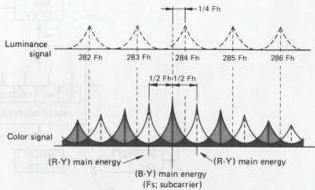
Fig. 1-1-21 Spectrum of color signal
In the phase shift system, the CH-1 component of the down converted color signal is distributed at 1/2 Fh intervals centered on the Fc (down converted color subcarrier) component. The CH-2 track component is delayed in phase 90° every line, deviated by 1/4 Fh, and distributed at 1/2 Fh intervals centered on Fc. This spectrum is shown in Fig. 1-1-22.
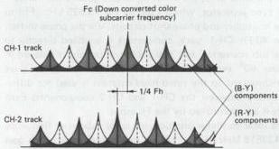
Fig. 1-1-22 Spectrum of down-converted color signal
The FM luminance and down converted color signals are mixed to become the recording current. When recorded and played back using magnetic tape, which processes 3-dimensional distortion and nonlinearity, interference in the form of \(F_0 + 2F_{DC}\) (Fo : FM carrier; FDC : down converted color signal) becomes introduced and cannot be ignored. When the 2FDC component is detected and demodulated, beat becomes produced with respect to the luminance signal and appears in the picture. Therefore, as with the color signal, Fc (down converted color subcarrier frequency) must be selected so that the 2FDC component becomes 1/4 offset in relation to the luminance signal, i.e.:
When Fc is determined at (40 Fh + 1/8 Fh), the spectrum of the CH-1 track B-Y component appears at (nFh + 1/8 Fh) and the R-Y component at (nFh - 3/8 Fh). In the CH-2 track distribution, B-Y appears at (nFh - 1/8 Fh) and R-Y at (nFh - 5/8 Fh).
Fig. 1-1-23 shows the 2 FDC component spectrum with respect to the playback luminance at this time.
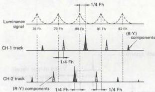
Fig. 1-1-23 2 FDC playback spectrum
The 2FDC components for both CH-1 and CH-2 become 1/4 line offset with respect to the luminance signal and thereby visually reduced. The 626.953 value was selected for both reducing noise and in consideration of color bandwidth.
3. Color signal recording bandwidth
Response curves for the highpass and lowpass filters are indicated in Fig. 1-1-24.
Constant current characteristics are possessed by the down-converted color signal recording current.
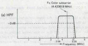
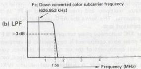
Fig. 1-1-24 Color signal recording bandwidth
1.1.9 VHS color signal playback system (PAL)
The color signal playback system performs essentially the opposite function as the recording system. In addition, however, important corrections must be performed for color signal frequency and phase errors introduced by variations in tape speed and head rotation, and elasticity of the tape.
Fig. 1-1-25 indicates a simplified block diagram of this system.
Though a lowpass filter, the down converted color signal goes to the main converter. At this time, the down converted color subcarrier (Fc) contains an error component \((40\mathrm{Fh}^{\prime} + 1 / 8\mathrm{Fh}^{\prime}\pm \Delta \mathrm{f})\) due to mechanical factors of the heads and tape. \(\mathsf{Fh}^{\prime}\) varies with the tape speed as \(\mathsf{Fh}\pm \Delta \mathsf{Fh}\). \(\Delta f\) is the instantaneous error caused by head rotation irregularities and tape elongation and contraction.
The 40 Fh' frequency deviation component is compensated by supplying the video output signal to the horizontal sync separator, multiplier and phase shifter, and 40 Fh' to the sub converter. This forms the AFC (automatic frequency compensator) loop.
In the APC (automatic phase compensator) loop, the \(1/8\mathrm{F}^{\prime}\mathrm{h} \pm \Delta \mathrm{f}\) phase error component is compensated by comparing the burst component of the up converted playback color signal with the subcarrier frequency from the local oscillator and APC detector. A variable crystal oscillator (VXO) produces \((\mathrm{Fs} + 1/8\mathrm{Fh}^{\prime} \pm \Delta \mathrm{f})\) which goes to the sub converter. As a result, \((\mathrm{Fs} + 40\mathrm{Fh}^{\prime} + 1/8\mathrm{Fh}^{\prime} + \Delta \mathrm{f})\) is supplied as the main converter carrier input from the sub converter through a highpass filter.
By frequency conversion with Fc, the color subcarrier frequency of 4.433619 MHz, which is free from frequency and phase deviations, becomes obtained through a bandpass filter. In the opposite manner as with recording, the phase shifter advances the CH-2 track phase \(90^{\circ}\) every line and 40 Fh' is supplied to the sub converter. The playback color signal through the main converter and bandpass filter is applied to a 2H delay line for removing crosstalk. Characteristics of the lowpass and bandpass filters are the same as those for recording (Fig. 1-1-24).
At the mixer, the playback color and luminance signals are mixed to become the video output signal.
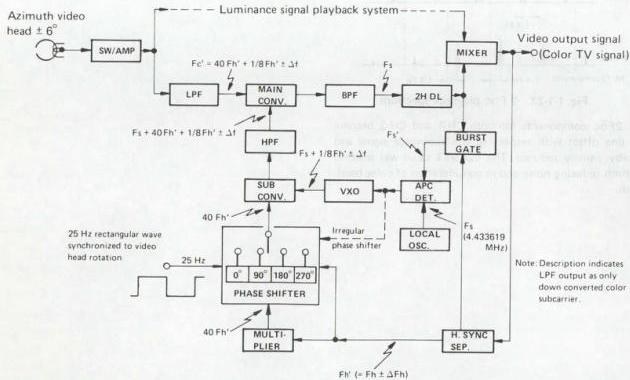
Fig. 1-1-25 Color signal playback system
1.1.10 VHS color signal recording system (SECAM)
1. SECAM color television signal
The SECAM color signal consists mainly of the following three component signals.
1) Synchronization ("sync") 2) Luminance ("Y") 3) Chrominance ("chroma")
Of these, the sync and luminance signals are processed in the same manner as for the PAL and NTSC systems. The principal differing point is that the chroma signal is frequency modulated and superimposed on the luminance signal.
The SECAM color signal is frequency modulated in order to avoid color hue fluctuations due to phase distortion in the transmitting system. Alternating lines are used for the modulated R-Y and B-Y signals. Two subcarrier frequencies are employed: 282 Fh = 4.40625 MHz (Fh = 15.625 kHz) for the R-Y component and 272 Fh = 4.25000 MHz for the B-Y component, which reduce the visible appearance Fo dot interference between the scanning lines.
To provide compatibility with B/W television, the signal goes through an anti-bell filter with a center frequency of 4.286 MHz. This attenuates the unmodulated carrier component, after which the signal is mixed with luminance.
Since pre-emphasis is applied prior to modulation, the frequency deviation range of the color FM carrier becomes 850 kHz between 3.9 MHz and 4.75 MHz. When the sidebands are included, the resulting range exceeds 2 MHz.
This model utilizes the VHS Hi-Fi format and records the SECAM color signal in the following manner.
1) The sync and luminance signals are frequency modulated (3.8 to 4.8 MHz) and recorded on the tape by rotating heads. 2) The 4 MHz color FM signal is counted down to approximately 1 MHz and recorded on the tape together with the luminance signal. 3) The longitudinal audio signal is recorded along the upper edge of the tape in the same manner as a conventional audio tape recorder. 4) In the VHS Hi-Fi system, audio signals are also frequency modulated and recorded helically by special rotary audio heads.
2. 1/4 frequency countdown recording
1) Color FM carrier bandwidth
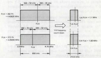
Fig. 1-1-27 Color FM carrier bandwidth
(a) Color FM carrier bandwidth (b) 1/4 frequency counted down color FM carrier bandwidth
Fig. 1-1-27 (a) indicates the FM carrier bandwidth of the color signal, while (b) shows the counted down bandwidth. By counting down the frequency 1/4th, the recording bandwidth becomes 1/4th and azimuth loss difference between high and low frequency components can be reduced.
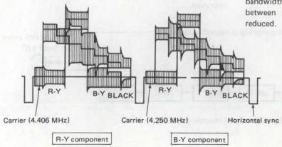
Fig. 1-1-26 SECAM signal waveform
2) Color signal horizontal correlation
The color FM signal pattern based on the horizontal correlation of section 1.1.3 - 3 is shown in Fig. 1-1-28.
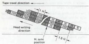
Fig. 1-1-28 Recording color signal pattern
As indicated, the pattern is distributed with a 1.5 H difference between adjacent tracks. The horizontal sync signals of adjacent tracks are arranged, while the R-Y and B-Y components become distributed between the adjacent track sync periods.
Consequently, in the same manner as the luminance signal, the color FM signal also possesses line and field correlations. The angular frequency difference between the playback main and crosstalk signals becomes nearly zero, while the demodulated crosstalk amount is very small compared to the main signal.
In this manner, the SECAM signal can be recorded in the VHS type format without using a guardband and without a crosstalk preventing circuit.
3) Modulation index
The color signal FM carrier covers the 850 kHz frequency range from 3.9 to 4.75 MHz, and when the FM waveform sidebands are included, the occupied range becomes more than 2 MHz. Since the sidebands remain unchanged even after 1/4th frequency countdown, they continue to cover the 2 MHz range centered on 1/4 FCR and 1/4 FCB.
However, after frequency countdown, the modulation index becomes 1/4th. Therefore, the sideband level is reduced about 10 dB with respect to the carrier component, which increases the margin for avoiding color reversal effects.
With a 1/4th modulation index, the required bandwidth for the color signal can be reduced to about 1/4th, thereby reducing the recording bandwidth by several hundred kHz. As a result, both sidebands of the color FM signal are recorded, reducing the likelihood of color reversal.
3. Recording block diagram
As simplified block diagram of the 1/4 frequency countdown direct recording system is shown in Fig. 1-1-29.
Bandpass filter BPF-1 separates the color component from the input video signal. The bell block functions to return the signal from the anti-bell characteristic used during transmission to a flat waveform which is easily counted down. The signal then goes through a limiter to the 1/4 frequency countdown circuit.
This circuit converts the color FM carrier form the 3.9 to 4.75 MHz range to the 0.98 to 1.19 MHz range. The next stage BPF-2 then limits the upper range of the frequency prior to mixing with the FM luminance signal.
In consideration of S/N and color reversal, the lower sideband is limited, after which the signal goes to the lowband anti-bell block. This circuit imparts an anti-bell characteristic to the counted down FM Carrier. The unmodulated carrier component is attenuated and S/N improved.

Fig. 1-1-29 Color signal recording system
1. Recording bandwidth
Fig. 1-1-30 illustrates the response curves of BPF-1 and BPF-2.
A constant current characteristic is used for recording the counted-down color signal.
The generalized characteristics of the bell and lowband anti-bell blocks for recording are shown in Fig. 1-1-31.
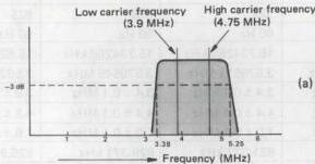
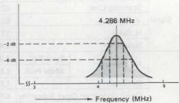
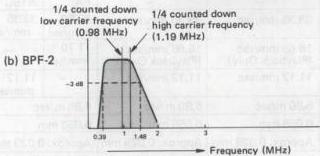
Fig. 1-1-30 Color signal recording bandwidth
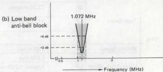
Fig. 1-1-31 Recording bell block characteristics
1.1.11 VHS color signal playback system (SECAM)
The simplified block diagram is shown in Fig. 1-1-32.
The lowband color FM signal is obtained by applying the playback signal to a lowpass filter. After shaping by the lowband bell block, the 4 times countup circuit returns the wide bandwidth of the color FM signal.
A bandpass filter yields the specified color signal bandwidth, after which the anti-bell block attenuates the unmodulated carrier component. The signal is then mixed with luminance to produce the video output signal.
Characteristic of the bandpass filter is the same as that of BPF1 indicated in Fig. 1-1-30, while the bell block characteristic is opposite to that shown in Fig. 1-1-31.
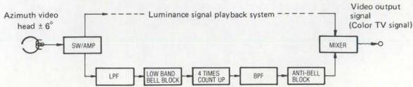
Fig. 1-1-32 Color signal playback system
1.1.12 M-PAL/N-PAL format outline
1. Specifications
| PAL | M-PAL | NTSC | N-PAL | ||||
|---|---|---|---|---|---|---|---|
| Signal | Color System | PAL | PAL | NTSC | PAL | ||
| Scanning Line | 625 | 525 | 525 | 625 | |||
| V. Sync | 50 Hz | 60 Hz | 60 Hz | 50 Hz | |||
| H. Sync | 15.625 kHz | 15.734266 kHz | 15.734266 kHz | 15.625 kHz | |||
| Subcarrier | 4.433619 MHz | 3.575611 MHz | 3.579545 MHz | 3.582056 MHz | |||
| VHS | FM Carrier | Sync Tip | 3.8 ± 0.1 MHz | 3.4 ± 0.1 MHz | 3.4 ± 0.1 MHz | 3.8 ± 0.1 MHz | |
| White Peak | 4.8 ± 0.1 MHz | 4.4 ± 0.1 MHz | 4.4 ± 0.1 MHz | 4.8 ± 0.1 MHz | |||
| Deviation | 1.0 ± 0.1 MHz | 1.0 ± 0.1 MHz | 1.0 ± 0.1 MHz | 1.0 ± 0.1 MHz | |||
| Down Converted Color Subcarrier | 625.953 kHz | 631.337 kHz | 629.371 kHz | 626.953 kHz | |||
| Tape Speed | Format | - | - | - | PAL | NTSC | |
| SP | 23.39 mm/sec | 33.35 mm/sec | 33.35 mm/sec | 23.39 mm/sec | 33.35 mm/sec | ||
| LP | 11.70 mm/sec | 16.68 mm/sec (Playback Only) | 16.68 mm/sec (Playback Only) | 11.70 mm/sec | - | ||
| EP | - | 11.12 mm/sec | 11.12 mm/sec | - | 11.12 mm/sec | ||
| Writing Speed | 4.85 m/sec | 5.80 m/sec | 5.80 m/sec | 4.85 m/sec | |||
| Video Track Width | SP | 0.049 mm | 0.058 mm | 0.058 mm | 0.058 mm | ||
| LP | Approx. 0.025 mm | Approx. 0.029 mm | Approx. 0.029 mm | Approx. 0.029 mm | |||
| EP | - | Approx. 0.019 mm | Approx. 0.019 mm | Approx. 0.019 mm | |||
| Video Track Angle (Running) | 5° 57' 50.3" | 5° 58' 9.9" | 5° 58' 9.9" | 5° 57' 50.3" | |||
| RF | TV Broadcasting System | B, (I) | M | M | N | ||
| Scanning Lines | 625 | 525 | 525 | 625 | |||
| V. Sync | 50 Hz | 60 Hz | 60 Hz | 50 Hz | |||
| H. Sync | 15.625 kHz | 15.734266 kHz | 15.734266 kHz | 15.625 kHz | |||
| Subcarrier | 4.433619 MHz | 3.575611 MHz | 3.579545 MHz | 3.582056 MHz | |||
| Video Bandwidth | 5 MHz (5.5 MHz) | 4.2 MHz | 4.2 MHz | 4.2 MHz | |||
| Video Modulation System | AM | AM | AM | AM | |||
| Video Modulation Polarity | Negative | Negative | Negative | Negative | |||
| Channel Bandwidth | 7 MHz (8 MHz) | 6 MHz | 6 MHz | 6 MHz | |||
| fs - fp | 5.5 MHz (6.0 MHz) | 4.5 MHz | 4.5 MHz | 4.5 MHz | |||
| Video Modulation System | FM | FM | FM | FM |
Table 1-1-2 Specifications
1.1.13 Luminance signal recording system (M-PAL)

Fig. 1-1-33 Luminance signal recording system
Frequency modulation (FM) is used for the luminance signal recording system. A simplified block diagram of the system is shown in Fig. 1-1-33.
A lowpass filter (LPF) removes the color component and passes only the luminance component of the input color TV signal. At the next stage, the pre-emphasis circuit, the high frequency portion of the luminance signal is enhanced in order to improve the S/N ratio during FM recording. Since excess pre-emphasis could lead to black/white reversal due to the shortened recording wavelength, a white/dark clip circuit cuts the overshoot and under-shoot components which exceed certain positive and negative levels.
The frequency modulator (FM MOD) converts the AM luminance signal to FM, which goes through a highpass filter (HPF) to the recording amplifier. These circuits amplify the signal with the proper frequency characteristic, after which it is mixed with the down converted color signal and supplied to the video heads.
1. Luminance signal recording frequency characteristic
As shown in Fig. 1-1-34, when the video input is a color TV signal, a lowpass filter removes the color component.
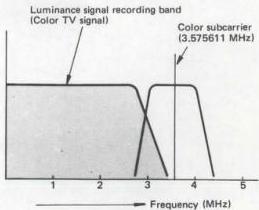
Fig. 1-1-34 Luminance signal recording band
This leaves the luminance signal, with a bandwidth from about \(30\mathrm{Hz}\) to \(3.0\mathrm{MHz}\). With some VHS models, when the input is a black and white TV signal, it by-passes the LPF; allowing a wider bandwidth (to beyond \(4.5\mathrm{MHz}\)).
2. FM signal recording frequency
As indicated in Fig. 1-1-35, when the video input is a color TV signal, it goes through an HPF, clearing an area for the down-converted color signal. With some VHS models, when the input is a B/W TV signal, the HPF can be bypassed to extend the bandwidth to the DC area.

Fig. 1-1-35 Recording spectrum
3. FM signal recording amp. current (REC amp)
Current:
| More than 3.4 MHz | : | Optimum saturation recording current |
|---|---|---|
| 2 MHz | : | 3 ± 1 dB |
| 1 MHz | : | 6 ± 1.5 dB |
| Less than 1 MHz | : | Flat characteristics |
Note: 0 dB at 3.4 MHz
4. FM signal head current (Video head)
Specified to be within \(\pm 1.5\) dB of 4 MHz optimum recording current.
1.1.14 Luminance signal playback system (M-PAL)
This system functions to return the signals recorded on the tape to a form as close as possible to the video input signals. The simplified block diagram is shown in Fig. 1-1-36.
The low level FM signals played back by the video heads are combined into a single FM signal by the switching amplifier. After amplification to the required frequency characteristic, a highpass filter attenuates the down converted color signal and passes only the FM luminance signal. This HPF has the same response as that of the recording system.
Variations in the playback FM signal level due to mechanical stretching and contraction of the tape, and irregularities in tape to head contact, are corrected by the limiter circuit. The signal is amplified more than 80 dB to permit precise demodulation. A double limiter circuit is employed in order to prevent black/white reversal effects.
In the following stages, the demodulator and lowpass filter return the luminance signal to its AM form. The de-emphasis circuit reverses the emphasis applied during recording. From this point, the signal goes to the mixer where it is mixed with the playback color signal to become the video output signal.

Fig. 1-1-36 Luminance signal playback system
1.1.15 Color signal recording system (M-PAL)
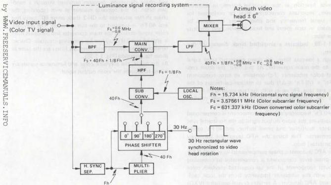
Fig. 1-1-37 Color signal recording system
This is a direct recording system using a down converted phase shifted color signal. The phase shift system removes color crosstalk which cannot be completely eliminated by the azimuth video heads. Fig. 1-1-37 illustrates a simplified block diagram of this system.
A bandpass filter (BPF) extracts the color component from the input video signal and supplies it to the main converter. At the same time, the input signal also goes to the horizontal sync separator, which supplies the 15.734 kHz (Fh) to the multiplier and phase shift circuits. Via the phase shifter, the 40 Fh CH-1 track component is supplied directly to the sub converter, but the CH-2 component is delayed in phase 90° every line (1 H). A 30 Hz rectangular wave synchronized to the video head rotation is used for differentiating between the CH-1 and CH-2 components. Each line is also controlled by the Fh input.
The local oscillator produces the color subcarrier frequency 3.575611 MHz (Fs) + 1/8 Fh single frequency which goes to the sub converter. At the sub converter, the 40 Fh and (Fs + 1/8 Fh) are frequency converted to become (Fs + 40 Fh + 1/8 Fh). This is supplied through a highpass filter to the main converter. Also supplied to the main converter are the color signal Fs +0.6 MHz and carrier wave (Fs + 40 Fh +1/8 Fh). These are down converted to become (40 Fh + 1/8 Fh +0.6 MHz) which through a lowpass filter goes to the mixer for mixing with the FM luminance signal. The result is applied to the video heads.
In other words, the 3.575611 MHz (Fc) color subcarrier is converted to a low band of 631.337 kHz (40 Fh + 1/8 Fh). The down converted color signal is then recorded directly using the FM luminance signal as AC bias.
1. Color signal recording bandwidth
Response curves for the highpass and lowpass filters are indicated in Fig. 1-1-38.
Constant current characteristics are possessed by the down-converted color signal recording current.
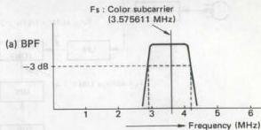
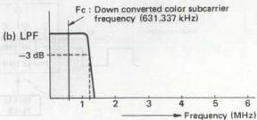
Fig. 1-1-38 Color signal recording bandwidth
1.1.16 Color signal playback system (M-PAL)
The color signal playback system performs essentially the opposite function as the recording system. In addition, however, important corrections must be performed for color signal frequency and phase errors introduced by variations in tape speed and head rotation, and elasticity of the tape.
Fig. 1-1-39 indicates a simplified block diagram of this system.
Though a lowpass filter, the down converted color signal goes to the main converter. At this time, the down converted color subcarrier (Fc) contains an error component \((40\mathrm{Fh}^{\prime} + 1 / 8\mathrm{Fh}^{\prime}\pm \Delta \mathrm{f})\) due to mechanical factors of the heads and tape. \(\mathsf{Fh}^{\prime}\) varies with the tape speed as \(\mathsf{Fh}\pm \Delta \mathsf{Fh}\). \(\Delta f\) is the instantaneous error caused by head rotation irregularities and tape elongation and contraction.
The 40 Fh' frequency deviation component is compensated by supplying the video output signal to the horizontal sync separator, multiplier and phase shifter, and 40 Fh' to the sub converter. This forms the AFC (automatic frequency compensator) loop.
In the APC (automatic phase compensator) loop, the \(1/8\mathrm{Fh}^{\prime}\pm \Delta \mathrm{f}\) phase error component is compensated by comparing the burst component of the up converted playback color signal with the subcarrier frequency from the local oscillator and APC detector. A variable crystal oscillator (VXO) produces \((\mathrm{Fs} + 1/8\mathrm{Fh}^{\prime}\pm \Delta \mathrm{f})\) which goes to the sub converter. As a result, \((\mathrm{Fs} + 40\mathrm{Fh}^{\prime} + 1/8\mathrm{Fh}^{\prime} + \Delta \mathrm{f})\) is supplied as the main converter carrier input from the sub converter through a highpass filter.
By frequency conversion with Fc, the color subcarrier frequency of 3.575611 MHz, which is free from frequency and phase deviations, becomes obtained through a bandpass filter. In the opposite manner as with recording, the phase shifter advances the CH-2 track phase \(90^{\circ}\) every line and 40 Fh' is supplied to the sub converter. The playback color signal through the main converter and bandpass filter is applied to a 2H delay line for removing crosstalk. Characteristics of the lowpass and bandpass filters are the same as those for recording (Fig. 1-1-38).
At the mixer, the playback color and luminance signals are mixed to become the video output signal.
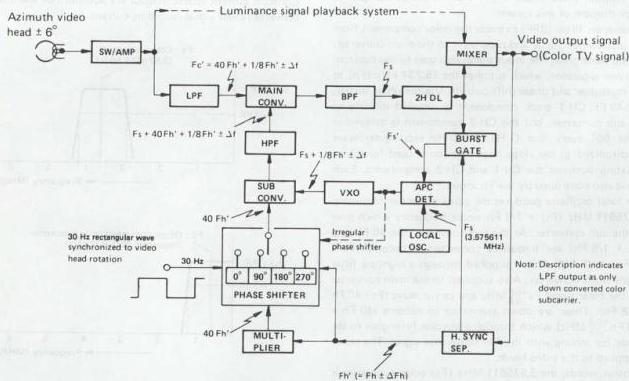
Fig. 1-1-39 Color signal playback system
1.1.17 Luminance signal recording system (N-PAL)

Fig. 1-1-40 Luminance signal recording system
Frequency modulation (FM) is used for the luminance signal recording system. A simplified block diagram of the system is shown in Fig. 1-1-40.
A lowpass filter (LPF) removes the color component and passes only the luminance component of the input color TV signal. At the next stage, the pre-emphasis circuit, the high frequency portion of the luminance signal is enhanced in order to improve the S/N ratio during FM recording. Since excess pre-emphasis could lead to black/white reversal due to the shortened recording wavelength, a white/dark clip circuit cuts the overshoot and undershoot components which exceed certain positive and negative levels.
The frequency modulator (FM MOD) converts the AM luminance signal to FM, which goes through a highpass filter (HPF) to the recording amplifier. These circuits amplify the signal with the proper frequency characteristic, after which it is mixed with the down-converted color signal and supplied to the video heads.
1. Luminance signal recording frequency characteristic
As shown in Fig. 1-1-41, when the video input is a color TV signal, a lowpass filter removes the color component. This leaves the luminance signal, with a bandwidth from about 30 Hz to 3.0 MHz. With some VHS models, when the input is a black and white TV signal, it by-passes the LPF; allowing a wider bandwidth (to beyond 4.5 MHz).
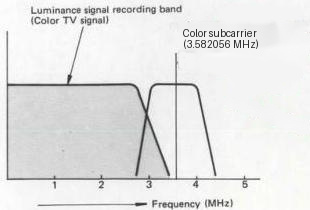
Fig. 1-1-41 Luminance signal recording band
2. White and Dark clip level
White clip level and dark clip level are as shown in Fig. 1-1-42.
Note: The level from sync tip to white peak is 100%.
3. FM carrier frequency and deviation
(See Fig. 1-1-42.)
Sync tip : 3.4 ± 0.1 MHz White peak : 4.4 ± 0.1 MHz Deviation : 1.0 ± 0.1 MHz
4. FM signal recording frequency
As indicated in Fig. 1-1-42, when the video input is a color TV signal, it goes through an HPF, clearing an area for the down converted color signal. With some VHS models, when the input is a B/W TV signal, the HPF can be bypassed to extend the bandwidth to the DC area.
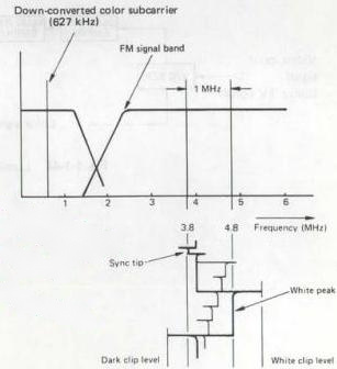
Fig. 1-1-42 Recording spectrum
1.1.18 Color signal recording bandwidth (N-PAL)
Response curves for the bandpass and lowpass filters are indicated in Fig. 1-1-43.
Constant current characteristics are possessed by the down-converted color signal recording current.
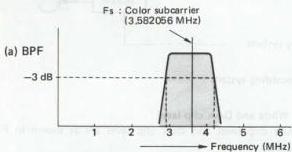
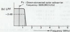
Fig. 1-1-43 Color signal recording bandwidth
1.1.19 S-VHS luminance signal recording system
Frequency modulation (FM) is used for the luminance signal recording system. A simplified block diagram of the system is shown in Fig. 1-1-44.
A Y/C separator removes the color component and passes only the luminance component of the input color TV signal. At the next stage, the sub pre-emphasis and the main pre-emphasis circuits, the high frequency portion of the luminance signal is enhanced in order to improve S/N during FM recording. Since excess pre-emphasis could lead to black/white reversal due to the shortened recording wavelength, a white/dark clip circuit cuts the overshoot and undershoot components which exceed certain positive and negative levels.
The frequency modulator (FM MOD) converts the AM luminance signal to FM, which goes to the recording amplifier. These circuits amplify the signal with the proper frequency characteristic, after which it is mixed with the down-converted color signal and supplied to the video heads.

Fig. 1-1-44 Luminance signal recording system
1. Luminance signal recording frequency characteristics
As shown in Fig. 1-1-45, when signal input is a video signal, a Y/C separator removes the color component and the luminance signal, with a bandwidth of from about 30 Hz to 5.0 MHz, is used.
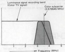
Fig. 1-1-45(A) Luminance signal recording band (NTSC)
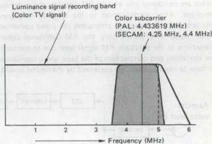
Fig. 1-1-45(B) Luminance signal recording band (PAL/SECAM)
2. White and dark clip level
White clip level and dark clip level are as shown in Fig. 1-1-46.
Note: The level from sync tip to white peak is 100%.
3. FM carrier frequency and deviation (See Fig. 1-1-46.)
Sync tip : 5.4 ± 0.1 MHz White peak : 7.0 ± 0.1 MHz Deviation : 1.6 ± 0.1 MHz
4. FM signal recording frequency
Fig. 1-1-46 shows recording spectrum when signal input is a video signal.
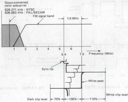
Fig. 1-1-46 Recording spectrum
5. FM signal recording amp. characteristic (REC amp)
Current: More than 5.4 MHz : Corresponds to the reference RF recording current 3 MHz : 0.5 ± 0.5 dB (0 dB at 5.4 MHz) 1 MHz : 3 ± 1 dB
6. FM signal head current (video head)
It shall be ±1.5 dB of the reference RF recording current.
1.1.20 S-VHS luminance signal playback system
This system functions to return the signals recorded on the tape to a form as close as possible to the video input signals. The simplified block diagram is shown in Fig. 1-1-47.
The low level FM signals played back by the two video heads are combined into a single FM signal by the switching amplifier. After amplification to the required frequency characteristic, an equalizer attenuates the down converted color signal and passes only the FM luminance signal. Variations in the playback FM signal level due to mechanical stretching and contraction of the tape, and irregularities in tape to head contact, are corrected by the limiter circuit.
The signal is amplified more than 80 dB to permit precise demodulation. A double limiter circuit is employed in order to prevent black/white reversal effects.
In the following stages, the demodulator and lowpass filter return the luminance signal to its AM form. The de-emphasis circuit reverses the emphasis applied during recording. From this point, the signal goes to the mixer where it is mixed with the playback color signal to become the video output signal.

Fig. 1-1-47 Luminance signal playback system
1.1.21 Control signal recording system
Control signal waveform, polarity and video head relationships are indicated in Fig. 1-1-48.
Phase of the control signal is the same as the vertical sync signal rise component of the CH-1 track. The positive pulse voltage is the reference 30 Hz (NTSC) or 25 Hz (PAL/SECAM). The control signal is recorded on the control track above the saturation recording level.
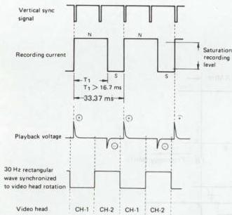
Fig. 1-1-48(A) Control signal (NTSC)
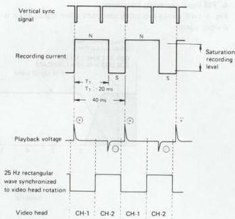
Fig. 1-1-48(B) Control signal (PAL/SECAM)
1.1.22 Audio signal recording system
1. Audio signal recording level
Audio signals are recorded on the longitudinal audio tracks to the defined level, using an AC bias current recording system.
2. Audio signal recording current characteristics
The equalizing amplifier controls the recording current in order to obtain a flat frequency characteristic in the reproduced output. See Fig. 1-1-49.
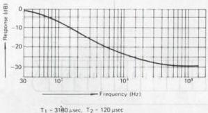
Fig. 1-1-49 Audio equalizing frequency characteristics
1.1.23 CTL coding system ("INDEX" system)
1. Outline
A newly developed "Index" system functions to locate the start of a desired program ("Index"). This operation relays a new CTL coding system which is described in this guide.
2. CTL coding system
As illustrated in Fig. 1-1-50, the 30 Hz (NTSC) or 25 Hz (PAL/SECAM) control (CTL) signal is produced in synchronization with the falling edge of the input V. sync. In the previous VHS standards, the CTL signal duty cycle (T1) was specified for greater than 16.67 ms (NTSC) or 19.82 ms (PAL/SECAM) (greater than 50%). Therefore, difference in the duty cycle occurred according to model and maker.
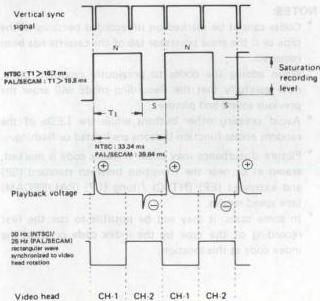
Fig. 1-1-50
The VHS standards have been revised to include stricter specification for the CTL signal, thereby allowing the inclusion of random access functions based upon coding of the duty cycle. These form the basis for the control coding system.
3. Control signal recording
The control signal is encoded and recorded in the forms illustrated in Fig. 1-1-51. Data are encoded by varying the duty cycle as shown.

Fig. 1-1-51 Data are encoded by varying in the duty cycle
For VHS models without the random access functions as well, the duty cycle has been specified as \(60 \pm 5\%\).
4. Overwrite function
When data are overwritten by using the same VHS machine, confirm that the residual signal level is less than \(-20\) dB with respect to the newly recorded control signal. This is important in order to ensure proper waveform shaping.
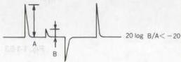
Fig. 1-1-52
5. Index code principle
1) Index code
The index code serves the same purpose as the 'cue' signal provided in some previous models. It allows locating the start of recorded programs on the tape.
However, the cue signal was recorded over the entire width of the tape, while the index signal is produced by changing the duty cycle of the control signal. Also, the cue signal was only inserted automatically at the start of recording.
When recording is initiated from Timer or Stop settings, the index code is automatically inserted.
Index code search is performed in the Fast Forward (FF), Rewind (REW), Search Fast Forward (S-FF) and Search Rewind (S-REW) modes. 2) Index code composition
Fig. 1-1-53 illustrates the composition of the index code. The code is comprised in \(61 \pm 3\) bits of data "1" with a data "0" bit at each end.
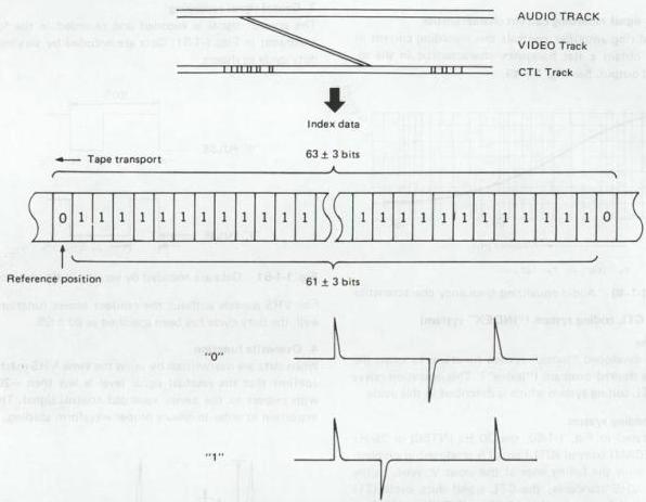
Fig. 1-1-53 Composition of the index code
6. Index code marking
1) Automatic index code marking When recording begins from the Timer Recording or Stop position, the index code is automatically inserted.
NOTES:
- Codes cannot be marked on unrecorded portions of the tape or if the erase protector tab of the cassette has been removed.
- When adding the codes to previously recorded tapes, note carefully that the Recording mode will erase the previous sound and picture.
- Avoid pressing other buttons while the LEDs of the random access function buttons are lighted or flashing.
- Picture disturbance may occur if index code is marked, erased at or near the transition between standard (SP) and extended (EP) (NTSC) / long (LP) (PAL/SECAM) tape speed modes.
- In some cases, it may not be possible to cue the first recording of the tape by the index code or erase the index code at this location.
1.1.24 VHS Hi-Fi system
1. Hi-Fi recording system
As can be noted from the VHS recording spectrum (Fig. 1-1-54), there is a relatively vacant slot between the color and luminance signal components.
Therefore, it was decided to modulate the stereo audio channels by frequency and to insert them into the spectrum at the 1.3 MHz (NTSC) / 1.4 MHz (PAL/SECAM) and 1.7 MHz (NTSC) / 1.8 MHz (PAL/SECAM) positions.
2. VHS Hi-Fi audio specifications
Recording system: The 2-channel audio signal is converted into two FM signal frequencies. These are recorded by special rotary heads. Afterwards, the video heads recorded the video signal overlapped. In the case of a monaural audio signal, the same signal is recorded on both audio channels.
Center carrier frequency CH-1 : 1.3 MHz } NTSC CH-2 : 1.7 MHz } PAL/SECAM CH-1 (Main) : 1.4 MHz CH-2 (Sub) : 1.8 MHz
Maximum frequency deviation : ±150 kHz Operating frequency deviation : ±50 kHz Pre-emphasis time constant : 50 µsec Audio head azimuth angle : ±30° Noise reduction system * Compression ratio : 2 : 1 logarithmic Detection system : Peak detection Frequency response : 20 Hz to 20,000 Hz Dynamic range : More than 80 dB Wow and flutter : Less than 0.005% WRMS Channel separation : More than 60 dB
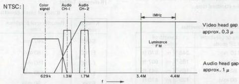
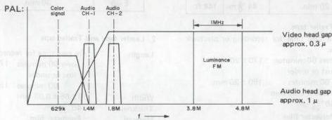
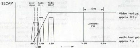
Fig. 1-1-54 VHS Hi-Fi recording spectrum
1.1.25 Cassette : NTSC
1. Video tape
Length : The relationship between tape length and time for recording and playback can be defined by the formula:
Where, L : tape length (m) t : recording or playback time (minutes)
Note: L shall be an integer obtained after all decimals produced in calculation are raised. (See "Reference Table".)
Width : \(12.65 \pm 0.01 \text{ mm}\)
Fluctuation: less than \(6 \mu \text{m}\)
Thickness : \(19_{-2}^{+1} \mu \text{m}\)
Coercivity : 600 oersted class (nominal)
Optimum recording current shall not differ from the standard tape.
[Reference Table]
| Kinds of blank cassettes | |||
|---|---|---|---|
| Kind of cassette | Recording or playback time in SP mode | Length of video tape | |
| T-120 | 120 min. | 246+3 | |
| 0 m | 870 ft | ||
| T-90 | 90 min. | 185+3 | |
| 0 m | 607 ft | ||
| T-80 | 80 min. | 165+3 | |
| 0 m | 541 ft | ||
| T-60 | 60 min. | 125+3 | |
| 0 m | 410 ft | ||
| T-40 | 40 min. | 84+3 | |
| 0 m | 276 ft | ||
| T-30 | 30 min. | 64+3 | |
| 0 m | 210 ft | ||
| T-20 | 20 min. | 44+3 | |
| 0 m | 144 ft |
2. Leader tape and Trailer tape
Length : In case time for recording or playback is: over 60 minutes : \(170 \pm 20 \text{ mm}\) just or under 60 minutes : \(150 \pm 20 \text{ mm}\)
Width : \(12.65 \pm 0.03 \text{ mm}\)
Thickness : \(40_{-25}^{+5} \mu \text{m}\)
Material : Polyester film
Transparency : more than \(50\%\)
Length of splicing: \(12 \sim 19 \text{ mm}\)
Gap of splicing : \(0 \sim 70 \mu \text{m}\)
Splicing force : more than \(3 \text{ kg}\)
3. Reel
Outside diameter : \(89 \pm 0.2 \text{ mm}\)
Hub diameter : In case time for recording or playback is: over 60 minutes : \(26 \pm 0.15 \text{ mm}\) just or under 60 minutes : \(62 \pm 0.2 \text{ mm}\) (If just or under 30 minutes, it can be \(70 \pm 0.2 \text{ mm}\).)
E-value : more than \(1.5 \text{ mm}\)
1.1.26 Cassette : PAL/SECAM
1. Video tape
Length : The relationship between tape length and time for recording and playback can be defined by the formula:
where, L : tape length (m) t : recording or playback time (minutes)
Note: L shall be an integer obtained after all decimals produced in calculation are raised. (See "Reference Table".)
Width : \(12.65 \pm 0.01 \text{ mm}\)
Fluctuation : less than \(6 \mu \text{m}\)
Thickness : \(19_{-2}^{+1} \mu \text{m}\) (Except E-240 tape).
Coercivity : 600 oersted class (nominal)
Optimum recording current shall not differ from the standard tape.
[Reference Table]
| Kinds of blank cassettes | ||
|---|---|---|
| Kind of cassette | Recording or playback time | Length of video tape |
| E-240 | 240 min. | 344+2 |
| 0 m | ||
| E-180 | 180 min. | 258+3 |
| 0 m | ||
| E-150 | 150 min. | 215+3 |
| 0 m | ||
| E-120 | 120 min. | 173+3 |
| 0 m | ||
| E-90 | 90 min. | 130+3 |
| 0 m | ||
| E-60 | 60 min. | 88+3 |
| 0 m | ||
| E-30 | 30 min. | 45+3 |
| 0 m |
2. Leader tape and Trailer tape
Length : In case time for recording or playback is: over 90 minutes : \(170 \pm 20 \text{ mm}\) just or under 90 minutes : \(150 \pm 20 \text{ mm}\)
Width : \(12.65 \pm 0.03 \text{ mm}\)
Thickness : \(40_{-25}^{+5} \mu \text{m}\)
Material : Polyester film
Transparency : more than \(50\%\)
Length of splicing: \(12 \sim 19 \text{ mm}\)
Gap of splicing : \(0 \sim 70 \mu \text{m}\)
Splicing force : more than \(3 \text{ kg}\)
3. Reel
Outside diameter : \(89 \pm 0.2 \text{ mm}\)
Hub diameter : In case time for recording or playback is: over 90 minutes : \(26 \pm 0.15 \text{ mm}\) just or under 90 minutes : \(62 \pm 0.2 \text{ mm}\) (If just or under 30 minutes, it can be \(70 \pm 0.2 \text{ mm}\).)
E-value : more than \(1.5 \text{ mm}\)
1.1.27 VHS cassette (simplified illustrations)
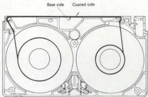
Fig. 1-1-55 Tape winding and tape path
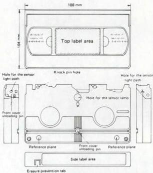
Fig. 1-1-56 Cassette appearance
1.1.28 S-VHS cassette
- VHS size with identification hole
- S-VHS tape is manufactured to newly established ratings and is important for deriving the S-VHS picture quality features.
- A special identification hole is provided in the S-VHS cassette for automatic detection by S-VHS type video cassette recorders.
- S-VHS cassettes can also be recorded in the standard VHS mode and played on ordinary VHS video cassette recorders.
1. Video tape
Specially formulated 1/2-inch wide magnetic tape that conforms to S-VHS performance ratings.
Length : The relationship between tape length and time for recording and playback can be defined by the formula:
where, L : tape length (m) t : recording or playback time (minutes)
Note: L shall be an integer obtained after all decimals produced in calculation are raised. (See "Reference Table".)
Width : \(12.65 \pm 0.01 \mathrm{~mm}\)
Fluctuation : less than \(6\mu \mathrm{m}\)
Thickness : \(19_{-2}^{+1}\mu \mathrm{m}\)
Coercivity : 600 oersted class (nominal) Optimum recording current shall not differ from the standard tape.
[Reference Table] : NTSC
Kinds of blank cassettes
| Kind of cassette | Recording or playback time in SP mode | Length of video tape | |
|---|---|---|---|
| ST-120 | 120 min. | 246^{+3}_{0} m | 870 ft |
| ST-60 | 60 min. | 125^{+3}_{0} m | 410 ft |
| ST-30 | 30 min. | 64^{+3}_{0} m | 210 ft |
| [Reference Table] : PAL/SECAM | |||
| Kinds of blank cassettes |
| Kind of cassette | Recording or playback time | Length of video tape |
|---|---|---|
| SE-180 | 180 min. | 258+3 |
| 0 m | ||
| SE-150 | 150 min. | 215+3 |
| 0 m | ||
| SE-120 | 120 min. | 173+3 |
| 0 m | ||
| SE-90 | 90 min. | 130+3 |
| 0 m | ||
| SE-60 | 60 min. | 88+3 |
| 0 m | ||
| SE-30 | 30 min. | 45+3 |
| 0 m |
2. Simplified illustrations
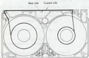
Fig. 1-1-57 Tape winding and tape path
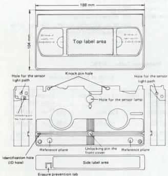
Fig. 1-1-58 Cassette appearance
1.2 S-VHS NEW TECHNOLOGY
1.2.1 General description
S-VHS was developed on the basis of the world-recognized VHS Format in order to accommodate higher picture quality broadcasts. The system is capable of recording and playback with signal quality exceeding present day TV transmission. It can thus meet the requirements of anticipated future high quality broadcasts.
The recording and playback horizontal resolution of the VHS Format is approximately 240 lines NTSC and 250 lines PAL/SECAM. The S-VHS system is capable of more than 400 lines resolution in all systems. The resolution of present broadcast pictures is about 350 lines, which is exceeded by the S-VHS capability.
1. Input connections
The S-VHS input and output connections differ according to the system. A 21-pin connector is used in Europe with switching between Y/C separate and composite signals. The NTSC system simply adds Y/C connections as indicated in Fig. 1-2-1 and Fig. 1-2-2.
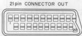
Fig. 1-2-1 (A)
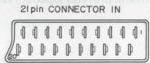
Fig. 1-2-1 (B)
| Pin No. | Composite | Y/C mode | RGB mode |
|---|---|---|---|
| 1 | Audio B out | Audio B out | Audio B out |
| 2 | — | — | — |
| 3 | Audio A out | Audio A out | Audio A out |
| 6 | — | — | — |
| 7 | — | — | B |
| 11 | — | — | G |
| 15 | — | C | R |
| 16 | Low | Low | High |
| 19 | CVBS | Y | — |
| 20 | — | — | — |
| Pin No. | Composite | Y/C mode | |
| --- | --- | --- | |
| 1 | — | — | |
| 2 | Audio B in | Audio B in | |
| 3 | — | — | |
| 6 | Audio A in | Audio A in | |
| 7 | — | — | |
| 11 | — | — | |
| 15 | — | C | |
| 16 | Low | Low | |
| 19 | — | — | |
| 20 | CVBS | Y |
Fig. 1-2-1 21-pin connector
2. Y/C connections
Fig. 1-2-1 and Fig. 1-2-2 indicate the Y/C connection ratings. Recording and playback through these connections are recommended for deriving maximum benefit from S-VHS performance. The Y/C separate connections can also be used for the VHS mode, where they offer the advantages of separate signal lines.

Fig. 1-2-2(A)

| Pin No. | Label |
|---|---|
| 1 | Y GND |
| 2 | C GND |
| 3 | Y out |
| 4 | C out |
Fig. 1-2-2(B)
S-VIDEO PLUG
| Pin No. | Label |
|---|---|
| 1 | Y GND |
| 2 | C GND |
| 3 | Y out |
| 4 | C out |
Fig. 1-2-2
Fig. 1-2-2 4-pin S connector
1.2.2 S-VHS and VHS differences
1. NTSC system
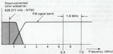
The main difference between S-VHS and VHS is in shifting the FM carrier to a higher frequency band, as indicated in Fig. 1-2-3. This permits resolution exceeding 400 lines even in the NTSC system. Also, in the NTSC system, the greater margin between the down converted color and luminance signals reduces interference between these signals.
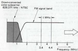
Fig. 1-2-3 NTSC FM carrier differences
2. European system
In Europe, a major difference with respect to VHS is that the same S-VHS system is used for both PAL and SECAM. Therefore, S-VHS mode recorded tapes are termed S-VHS Europe regardless of the TV broadcast system.
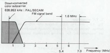
As indicated in Fig. 1-2-4, the FM carrier is shifted to a high frequency band in the same manner as NTSC. This expands the sideband width and provides superior resolution.
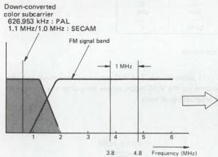
Fig. 1-2-4 PAL/SECAM FM carrier differences
Signal processing is the same for PAL and SECAM systems. This is outlined below.
1) PAL signal recording and playback
S-VHS recording of a PAL signal is essentially the same as VHS. Following Y/C separation, the luminance signal is converted to FM and the color signal is down converted for recording on the tape.
2) SECAM signal recording and playback
After Y/C separation, the color signal is detected to yield the R-Y and B-Y color difference signals. These are modulated at 4.43 MHz in the same form as a PAL signal, then sent to the recording converter circuit. The information is therefore recorded on the S-VHS tape without difference between PAL and SECAM.
3. Compatibility
1) NTSC system
Compatibility is not a problem with NTSC as there is basically only one system.
Note:
VHS playback of S-VHS tape
In S-VHS the FM carrier is shifted to high band. When an S-VHS tape is played back in VHS, FM carrier loss occurs and overmodulation noise appears as black stripes mainly in bright portions of the picture. In a bright picture, the luminance level is high. When this is frequency modulated, the FM deviation is large and increases the high frequency component. Overmodulation occurs with this high frequency component.
Conversely, the opposite effect occurs with a dark TV picture. When this (S-VHS signal) is played back in the VHS mode, a normal picture may be obtained without overmodulation.
2) European systems
Compatibility is somewhat complex among European models and should be noted carefully in service and in responding to customer inquiries.
(1) S-VHS for PAL market
PAL S-VHS is intended for use with PAL monitor. It cannot record a SECAM signal. However, it can play back a prerecorded S-VHS tape, whether PAL or SECAM.
(2) S-VHS for SECAM market
SECAM S-VHS models can record and play back both SECAM and PAL sigals. Playback is selectable for SECAM or PAL modes.
4. SECAM S-VHS recording and format
The same format is used for recording PAL and SECAM signals in the S-VHS Europe specifications. Therefore for models sold in SECAM areas (e.g., France) the recording format differs according to the S-VHS input signal and recording mode (S-VHS or VHS).
Recording
| Input signal | REC mode | Output signal (EE mode) | REC color signal system |
|---|---|---|---|
| SECAM | S-VHS SP/LP | SECAM | S-VHS |
| VHS SP | SECAM | SECAM | |
| PAL | S-VHS SP/LP | PAL | S-VHS |
| VHS SP/LP | PAL | PAL |
Playback
| REC signal & REC mode by Color TV system | | Output signal → Color TV system | | --- | --- | --- | | S-VHS | | PAL/SECAM | | VHS SECAM | SP | SECAM only | | | LP | PAL/SECAM | | VHS PAL VN/LD | | PAL/SECAM |
As indicated in Table 1-2-1, a SECAM input signal in the VHS LP mode becomes recorded on the tape in the PAL format. Prior to recording S-VHS, the color signal is detected to form the color difference signals, which are supplied to the PAL encoder. The resulting PAL signal is then sent to the recording circuit.
In normal VHS SECAM, the line sequential color signal format of SECAM is utilized so that essentially the same signal is recorded on adjacent tracks. During playback, effects from cross interference form the adjacent channel are nearly negligible.
However, in the LP mode, this correlation between tracks is lost. Therefore, normal VHS SECAM models use special narrow recording and playback heads for the LP mode in order to minimize adjacent track interference.
Since S-VHS Europe records not only SECAM but PAL as well, the head width is set to accommodate both systems. The LP head also uses a wider track in order to provide greater playback tracking margin.
In the S-VHS SECAM mode, the signal is recorded as a PAL or SECAM mode.
However, during VHS playback in the normal SECAM system (only a few normal VHS models are capable of LP mode playback), since the system in PAL, a SECAM signal is not obtained.
A PAL system recording played back on a SECAM S-VHS model is reproduced as PAL signal.
5. Cassettes
Mechanical specifications of the S-VHS cassette are the same as the normal VHS cassette. Therefore, an S-VHS cassette can be used in normal VHS models for recording and playback in the normal VHS mode.
The S-VHS tape uses a finer surface process in order to allow high frequency recording and playback. It is therefore capable of stable picture quality when used for VHS mode recordings.
1) S-VHS tape specifications
Tapes for use is S-VHS recording and playback are designated as follows.
| Designation | System |
|---|---|
| ST. ( indicates time) | NTSC |
| SE- ( indicates time) | PAL/SECAM |
| ST-C (* indicates time) | NTSC C cassette |
| SE-C (* indicates time) | PAL/SECAM C cassette |
Table 1-2-2 S-VHS tape specifications
Construction is the same as VHS cassette, except that S-VHS has a special identification hole for automatically detecting presence of an S-VHS cassette.
Video tape thickness is \(19 \pm 2 \mu \mathrm{m}\)
Electrical characteristics are those required for S-VHS. 2) S-VHS mode selection
Recording: S-VHS cassette detected and S-VHS mode switch position
Playback: S-VHS cassette detected and FM carrier format
Note: Presence of an S-VHS C cassette cannot be detected when used with some earlier types of cassette adapters.
6. Heads
Present day video heads include the advancements that have brought high performance video equipment. The main video head characteristics required for VHS products are as follows.
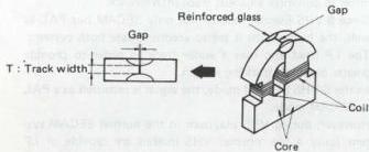
Fig. 1-2-5 Video head
1) High effective permeability
Current following in the head produces a magnetic flux. A magnetic field is then recorded on the tape. When the efficiency of this process is high, a large output can be obtained during playback.
2) Large maximum magnetic flux density
High performance tape possesses high magnetic resistance. A large flux density is therefore needed for recording. The magnetic flux density differs according to the head materials.
3) Low residual flux density
Although high magnetic flux density is desired, the residual flux density must be low. If this is high, the head will tend to erase the recorded information during playback. The reduced playback output impairs the playback S/N.
4) High resistance to abrasion
Since the head traverses the tape at high speed, abrasion wears the head and affects head life. The rate of abrasion depends on the head materials. Hard materials are thus desired.
1.2.3 S-VHS new technology
1. Input and output signal circuits
Input signal quality is important for deriving S-VHS performance. The Y/C separate inputs and outputs allow high picture quality and freedom from color dot noise in high frequency luminance signal components.
1) S-VHS input signals
| S-VHS input signal | Description |
|---|---|
| External input (composite video) | Standard signal supplied to the video input connector |
| Y/C separate inputs | Inputs (Y/C) for S-VHS supplied to Y/C separate input connector Y/C separate input signals supplied to 21 pin connector |
| TV signal | Video signal received by built-in tuner |
| Composite sync signal from TV supplied via 21 pin connector |
Table 1-2-3 S-VHS input signal
These are ordinary video signals, but as S-VHS has a wide recording signal bandwidth of 5 MHz, luminance and color cannot be separated by a simple lowpass filter such as used for VHS. Although separation is possible, beat interference would occur due to residual color component in the luminance signal and detract from picture quality.
Y/C separate input and output signals are therefore specified for S-VHS, since these do not require separation. These connections are presently found on new model TV receivers. While their use is expected to expand in the future, they are still comparatively rare among the general public.
At the present time, there are few input sources for S-VHS and most signals are composite. However, Y/C separate signals will become commonplace for video cameras, signal generators and TV broadcasts.
S-VHS models are therefore provided with both Y/C separate and composite signal connections. Special technology is used for Y/C separation of the composite signal. The quality of the separation circuit to a large extent determines the S-VHS performance.
Fig. 1-2-6 indicates the wide luminance signal frequency response. This is beyond the capability of a lowpass filter. Therefore, a logical comb filter circuit is used for separating the luminance and color signals.
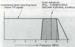
Fig. 1-2-6 PAL/SECAM luminance signal frequency spectrum
2. Y/C separation circuit
1) NTSC signal
As shown in Fig. 1-2-7, luminance and color signals are mixed in the input composite NTSC frequency response. In normal VHS, Y and C are separated by a comb filter.
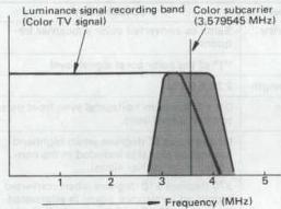
Fig. 1-2-7 NTSC luminance signal frequency spectrum
However, this would be inadequate for S-VHS because of the wide luminance signal band and residual color would appear as best interference during playback. A logical comb filter is therefore used in S-VHS for Y/C separation.
2) PAL/SECAM signal
The luminance signal band is wider than NTSC and the Y/C separation circuit is particularly important. As the color signal frequency is higher a simple lowpass filter circuit is adequate for normal VHS Y/C separation.
However, a logical comb filter is used for S-VHS because of the wide luminance signal band. With a SECAM input, a bell filter circuit is used for separation, after which only the color signal is converted to PAL for recording.
3. Recording processor circuit
The S-VHS recording processor is designed for common use with VHS. Circuit response is controlled by regulating signal flow through the filter circuit. Although the recording signal flow is more complex than VHS, it is basically the same.
1) Recording FM signal
As indicated in Fig. 1-2-8, the recording FM signal is shifted to high band due to the expanded recording frequency range. This provides a luminance signal recording band of 5 MHz. The FM carrier shift also widens the lower sideband range and high resolution beyond 400 lines is achieved.
The FM signal shift requires changes in the response of the recording emphasis, white and dark clip, playback FM equalizer and FM limiter circuits.
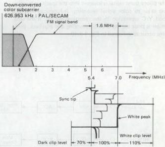
Fig. 1-2-8 S-VHS recording spectrum
4. Pilot burst signal
This signal is not required for NTSC system. In S-VHS Europe (PAL/SECAM) system, the pilot burst signal is needed for controlling Y/C separation response according to the TV signal characteristics.
As shown in Fig. 1-2-9, the pilot burst signal is inserted into the horizontal sync signal blanking interval and recorded on the S-VHS tape. This is used as the color signal subcarrier.
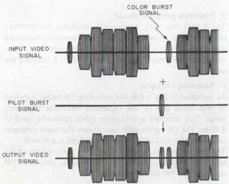
Fig. 1-2-9 Pilot burst signal
The piloty burst signal is inserted into the specified location just prior to color signal recording. It functions to detect good Y/C separation in the recording system. If the separation is poor during S-VHS recording and playback, problems occur as indicated in Fig. 1-2-10.
Good separation with Y/C or composite signal input: pilot burst signal phase is 90 degrees.
If separation is poor with composite input: pilot burst signal phase is 270 degrees.
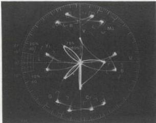
Fig. 1-2-10 Phase relation of pilot burst
1) Pilot burst signal specifications (S-VHS Europe system)
| Label | Specification |
|---|---|
| Frequency | Same as converted color subcarrier frequency |
| Level | “25% of the color burst signal level |
| Burst length | 2.26 ± 0.23μ |
| Position | 0.8 ± 0.3μs from horizontal sync front porch to burst signal start |
| Phase | 90 degrees ±10 degrees when highband luminance signal is included in the converted color carrier signal |
| 270 degrees ±10 degrees when converted recording luminance signal is attenuated more than 20 dB with respect to the color signal in the 1.2 MHz area |
Table 1-2-4 Pilot burst signal specification
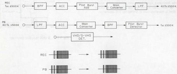
Fig. 1-2-11 Pilot burst circuit block
2) Circuit operation
As shown in Fig. 1-2-11, the S-VHS detector circuit inserts the pilot burst signal at the specified position during S-VHS recording. The signal is inserted in the final stage of the color signal processing circuit and recorded on the tape.
During playback, the S-VHS detector circuit detects the pilot burst signal phase and switches the S-VHS preamp filter. By detecting the pilot burst signal, the sideband signal in the 1.2 MHz area is cutoff, thereby avoiding color beat in the playback picture.
5. High resolution technology
S-VHS is capable of processing about 200 lines more data compared with VHS. This high resolution capability is made possible by shifting the FM carrier to highband, as indicated in Fig. 1-2-15.
(1) NTSC VHS system
In NTSC VHS, the carrier is 3.4 MHz and deviation is 1 MHz. Therefore, the sideband from the FM carrier center is about 3 MHz. The VHS resolution is about 240 lines.
Down-converted color subcarrier 629.371 kHz : NTSC FM signal band
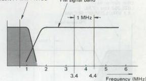
Fig. 1-2-13 NTSC recording spectrum
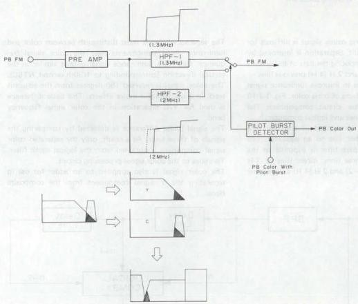
Fig. 1-2-12 Pilot burst detector circuit
(2) PAL VHS system
The PAL system video signal band is wider than NTSC at 5 MHz. If the same carrier as NTSC were used, the resolution would be lower. Therefore, the carrier frequency is raised to 3.8 MHz to provide a sideband width of 3.3 MHz and resolution of about 270 lies.
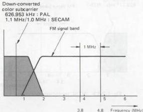
Fig. 1-2-14 PAL recording spectrum
6. Logical comb filter
Y/C separation with a varying coloror signal is difficult for an ordinary comb filter circuit. Separation is improved by the logical comb filter by computing the data of the present line, 1 H (2 H) previous line, and 2 H (4 H) previous line.
The logical comb filter serves to improve luminance signal resolution and reduce the effects of cross color. Fig. 1-2-16 shows the logical comb filter circuit composition. The circuit comprises two delay lines and logical computer.
The input composite signal is supplied in one line to a bandpass filter and in another line to an equalizer. The color signal from the bandpass filter is supplied to the logical comb computer in three lines: direct (line n), 1 H (2 H) delayed line n − 1 (n − 2) and 2 H (4 H) delayed line n − 2 (n − 4).
(3) S-VHS system
In S-VHS, the carrier frequency is raised to 7.0 MHz and sideband width is 5.0 MHz, thus enabling better than 400 lines resolution. This higher recording and playback frequency places greater demands on video tape and video head performance.
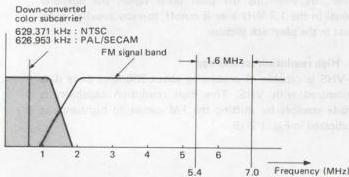
Fig. 1-2-15 S-VHS recording spectrum
The separation circuit must distinguish between color and luminance signal components near the color signal frequency. Generally, luminance signal data is similar in the vertical direction (corresponding to 1/30th second, NTSC). The color signal is reversed 180 degrees from the adjacent track in order to avoid moiré effects. This basic difference is used for Y/C separation in the color signal frequency band.
The signal phase difference is detected by comparing the signals of three lines. As a result, only the separated color signal component is obtained from the logical comb filter. This goes to the color signal processing circuit.
The color signal is also supplied to an adder for use in separating the Y signal component from the composite signal.
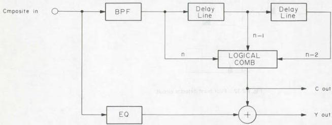
Fig. 1-2-16 Logical comb filter circuit
1) Circuit operation
S-VHS response is largely determined by the comb filter circuit for Y/C separation of the composite signal. As illustrated in Fig. 1-2-16, the data from the present line (n), the previous line (n − 1) and 2 lines previous (n − 2) are sent to the logical comb, which determines whether a signal component is luminance or color. This allows separation without loss in the highband luminance signal response. In the PAL color system, line correlation is every 2 H. Therefore, the logical comb filter compares line n, n − 2, and n − 4. Y/C signal leak is also absent, eliminating dot noise that occurs from inadequate separation.
The NTSC color signal frequency is lower than PAL and comb filters are found in some high quality VHS models. However, the effects of inadequate separation do not appear in the 3 MHz frequency band.
Fig. 1-2-16 indicates the input data of lines n, n − 1, and n − 2. Generally speaking, TV signal correlation is strong in the vertical direction. The luminance signal is the same phase, while the color signal is at opposite phase.
Therefore, when the computer compares the data of the 3 lines, if the variation is linear, a luminance signal can be determined. If the signal varies with each line, the signals color.
2) S-VHS Y/C separation importance
(1) Residual color in Y signal
Y edge moire: Interference with color signal
Dot interference
(2) Residual highband luminance in color signal
Cross color: S-VHS specification is −20 dB at 1.2 MHz
S-VHS is provided with Y/C separate inputs in order to avoid these effects by eliminating the need for separation.
3) Y/C separation effects on resolution
Presently, the composite signal is most often used as the S-VHS input. But the Y/C separation circuit considerably affects the S-VHS recording and playback response. When the color is at a high frequency position, as in the case of PAL/SECAM, the separation characteristics of the composite input signal are recorded as data on the tape. The signal bearing this separation data is termed the pilot burst signal.
Poor separation affects both the luminance and color systems in the S-VHS mode. In order to avoid beat interference during playback, the circuit functions to automatically attenuate the lower sideband and the luminance component within the color signal band.
As indicated in Fig. 1-2-17, residual color in the lower sideband and the down converted color signal become equal. The interleave relationship is lost and beat interference occurs.
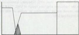
Fig. 1-2-17
A trap circuit for the 1 MHz area is therefore inserted into the playback system, cutting the signal component where beat occurs.
This circuit is not required when separation is good. The pilot burst signal is employed for detecting whether or not to insert the circuit.
7. Pre-emphasis response
In order to maintain compatibility with VHS, a sub-emphasis circuit for S-VHS is added to the pre-emphasis system. The S-VHS sub-emphasis response is indicated in Fig. 1-218 and Fig. 1-2-19. The peak point is in the area of 3 MHz, 2 MHz higher than VHS. Operation is basically the same as the non-linear emphasis circuit of VHS. The S-VHS emphasis circuit allows resolution in excess of 400 lines without impairing S/N.
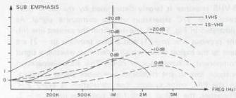
Fig. 1-2-19 Frequency characteristics
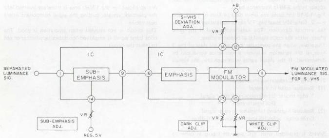
Fig. 1-2-18 Sub-emphasis and FM modulation circuit