JVC VIDEO TECHNICAL GUIDE VTG82063 - SECTION 2
MECHANISM DESCRIPTION
2.1 MECHANISM ADVANCES
The mechanical systems of home VTRs have been improved over the years to provide both easy use and to allow high performance functions such as editing.
The evolution in cassette housing design has brought easier usage by the customer, while improved tape loading systems allow editing and other sophisticated functions.
| CASSETTE LOADING TYPE /CASSETTE HOUSING | MODEL NAME | |||
|---|---|---|---|---|
| MECHANICAL (DOWN & LIFTING) | HR-2200 series | |||
| HR-3300 series | HR-3660 series | |||
| HR-4100 series | HR-6700 series | |||
| HR-7200 series | HR-7300 series | |||
| FRONT LOADING 1:FL-1 (Cassette motor via chain drive) | HR-7600 series | |||
| HR-7650 series | HR-7700 series | |||
| FRONT LOADING 2:FL-2 (Cassette motor via gear drive) | HR-D110 series | |||
| HR-D111 series | ||||
| HR-D120 series | ||||
| HR-D121EG | ||||
| HR-D130U | ||||
| HR-D131U | ||||
| HR-D140 series | HR-D141 series | |||
| HR-D142 series | ||||
| HR-D143 series | ||||
| HR-D150 series | ||||
| HR-D151 series | ||||
| HR-D152S | ||||
| HR-D156MS | HR-D157MS | |||
| HR-D158MS | ||||
| HR-D160EG | ||||
| HR-D220 series | ||||
| HR-D225 series | ||||
| HR-D250 series | ||||
| HR-D251 series | HR-D257MS | |||
| HR-D555U | ||||
| HR-D565 series | ||||
| HR-D566 series | ||||
| HR-D725 series | ||||
| HR-D756U | ||||
| HR-P50E | ||||
| FRONT LOADING 3:FL-3 (Cassette motor via belt drive) | HR-D160EN | |||
| HR-D170 series | ||||
| HR-D171 series | ||||
| HR-D180 series | ||||
| HR-D190 series | ||||
| HR-D210 series | ||||
| HR-D211EM | ||||
| HR-D217 series | HR-D227 series | |||
| HR-D230 series | ||||
| HR-D237U | ||||
| HR-D300 series | ||||
| HR-D3050U | ||||
| HR-D310 series | ||||
| HR-D321 series | ||||
| HR-D330 series | HR-D337MS | |||
| HR-D350MS | ||||
| HR-D360U | ||||
| HR-D370 series | ||||
| HR-D430 series | ||||
| HR-D440 series | ||||
| HR-D441EN | ||||
| HR-D530 series | HR-D570 series | |||
| HR-D630U | ||||
| HR-S5000 series | ||||
| HR-S5500 series | ||||
| HR-S7000U | ||||
| HR-S8000U | ||||
| HR-S9000EG | ||||
| SIDE LOADING 1:SL-1 (Cassette motor via gear drive) | HR-D470 series | |||
| FRONT LOADING 4:FL-4 (Cassette motor via belt drive) | HR-D410U | |||
| HR-D700U | ||||
| HR-D750 series | HR-D950 series | |||
| HR-S10000U | ||||
| FRONT LOADING 5:FL-5 (Mode motor via worm clutch drive) | HR-D1520 series | |||
| HR-D1830UM | ||||
| HR-D4050U | ||||
| HR-D520 series | ||||
| HR-D540 series | HR-D550 series | |||
| HR-D580 series | ||||
| HR-D600 series | ||||
| HR-D610 series | ||||
| HR-D620 series | HR-D641M | |||
| HR-D650MS | ||||
| HR-D660 series | ||||
| HR-D670U | ||||
| HR-D680U | HR-D830 series | |||
| HR-D850U | ||||
| HR-D870U | ||||
| HR-S6600U | ||||
| TRAY LOADING | HR-SC1000U | HR-FC100U | HR-FC100E/EG |
Table 2-1-1
2.1.1 Cassette loading systems (cassette housing)
There are two main types of cassette loading systems. First to appear was manual insertion and positioning. The cassette was inserted from the top, then the housing was pressed by hand for lowering it into position. Ejecting the cassette was by pressing a lever to release the lock, after which the cassette housing was raised by a spring. These operations required space above the VTR, while the action was said to be noisy and occasionally the cassette was dropped upon ejecting.
Front loading is the second system introduced with the HR-7650 series. This system uses a motorized housing and the VTR itself performs the operations after inserting the cassette. It is also quiet and conserves space. Subsequent to the HR-7650, most models use the front loading system.
There are presently 7 types of front loading cassette housings. These are indicated in Table 2-1-1 together with their main models.
1) Front loading 1 (FL-1) type
This cassette housing was adopted by the HR-7650 series. A distinguishing feature is the chain drive used for raising and lowering the cassette housing.
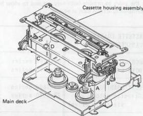
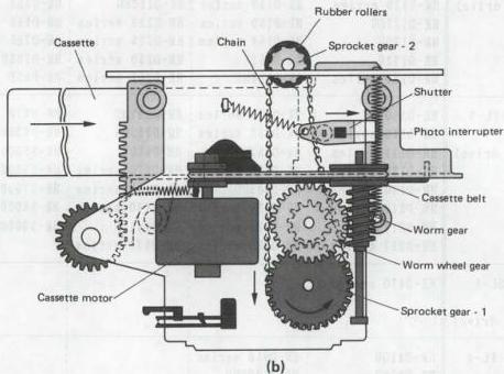
Fig. 2-1-1 Cassette housing mechanism (FL-1 type)
2) Front loading 2 (FL-2) type
The FL-2 system was introduced with the HR-D220 series. It features simplified construction compared with the FL-1, allows lighter weight slim product designs and uses more plastic parts. Cassette loading is performed only by gears.
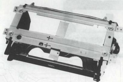
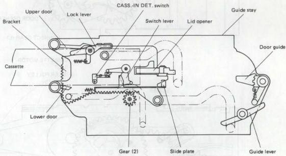
Fig. 2-1-2 Cassette housing mechanism (FL-2 type)
3) Front loading 3 (FL-3) type
The HR-D530 series was the first to use this type of cassette housing. It is further slimmer and more simplified than the FL-2 type. A gear operates the cassette door. If a cassette is absent at the loading complete state, the door is closed. The fluorescent display panel (FDP) indicates when a cassette is present.
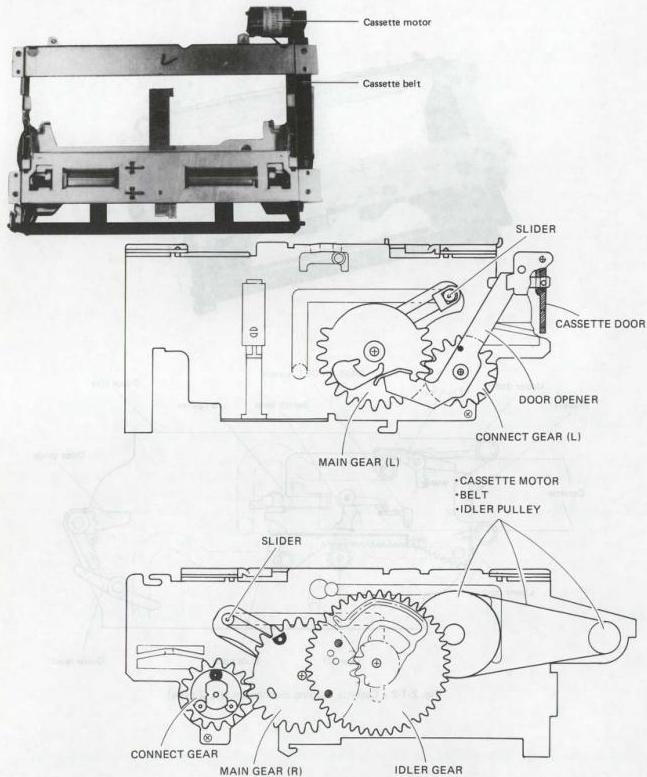
Fig. 2-1-3 Cassette housing mechanism (FL-3 type)
4) Slide loading 1 (SL-1) type
In this system, the cassette is inserted in the long direction. This allows slim width design equivalent to typical audio components. The SL-1 type first appeared with the HR-D470 series.
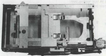
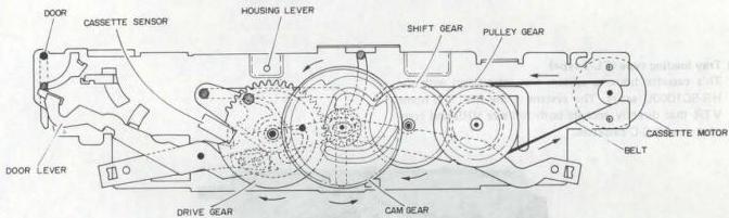
Fig. 2-1-4 Cassette housing mechanism (SL-1 type)
5) Front loading (FL-4) type
This was adopted in the HR-D410 series and is essentially an improved version of the FL-3 type.
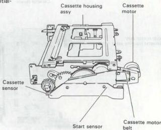
Fig. 2-1-5 Cassette housing mechanism (FL-4 type)
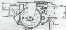
6) Front loading (FL-5) type
The FL-5 is the most recent version and was first used in the HR-D610 series. The cassette loading motor is not contained in the cassette housing assembly. The loading motor drive is transferred to the housing by the worm clutch assembly. Since the loading motor performs operations from cassette loading to tape loading, compact and lightweight designs are made possible.
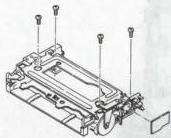
Fig. 2-1-6 Cassette housing mechanism (FL-5 type)
7) Tray loading type (TL-1 type)
This cassette housing system was introduced with the HR-SC1000U series. The system is the first in a home VTR that directly accepts both full size VHS and compact size VHS-C cassettes.
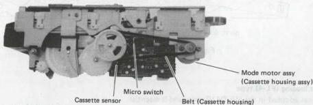
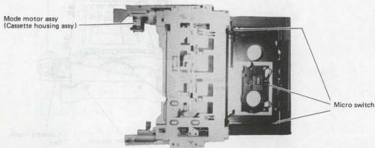
Fig. 2-1-7 Cassette housing mechanism (TL-1 type)
2.1.2 Tape loading methods
There are two main categories of loading methods: loading ring and loading arm.
1. Loading ring system
The loading ring system has been used since the first home VTR models. Presently, it is found mainly in VideoMovies. The mode control motor rotation is transferred by gears to the supply and take-up loading rings. Control is from the mechacon circuit and detection is by two mode sensors mounted on the loading gears. The mechanism provides good response for complex operations such as editing, but the number of component parts is comparatively large. The loading arm system was therefore adopted in order to reduce the number of parts and allow more compact and lightweight products.
2. Loading arm system
This system was introduced with the HR-D160 series. A belt transfers the mode control motor rotation to a worm gear. This drives a control cam or arm gear for operating the supply and take-up loading arms. Overall mechanism operation is controlled by mode control motor, control plate and control cam. The slide encoder detects the mechanism mode and transfers the data to the mechacon circuit. In addition to allowing compact and lightweight designs, the system features adaptability for complex operations by changing the control plate and slide encoder. The loading arm system is presently used in 8 models. The system relationships are indicated in Table 2-1-2.
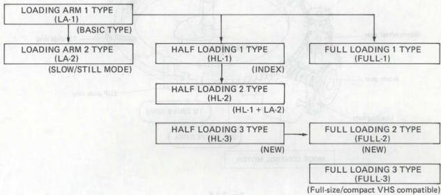
Table 2-1-2
3. Tape loading systems
This section outlines the tape loading mechanisms used in various models. It includes the major parts and mechanism timing charts.
1) Loading system
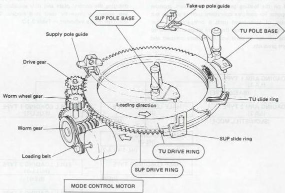
Fig. 2-1-8
| LOADING TYPE | MODEL NAME | |||
|---|---|---|---|---|
| LOADING RING | HR-2200 series | HR-7600 series | HR-D142 series | HR-D250 series |
| HR-3300 series | HR-7610MS | HR-D143 series | HR-D251 series | |
| HR-3320EK | HR-7650 series | HR-D150 series | HR-D257MS | |
| HR-3330 series | HR-7655 series | HR-D151 series | HR-D565 series | |
| HR-3600 series | HR-7700 series | HR-D152S | HR-D566 series | |
| HR-3660 series | HR-D110 series | HR-D156MS | HR-D725 series | |
| HR-4100 series | HR-D111 series | HR-D157MS | HR-D755 series | |
| HR-6700U | HR-D120 series | HR-D158MS | HR-D756U | |
| HR-7200 series | HR-D121 series | HR-D160EG | HR-S10 series | |
| HR-7300 series | HR-D140 series | HR-D220 series | ||
| HR-7350EK | HR-D141 series | HR-D225 series |
Table 2-1-3
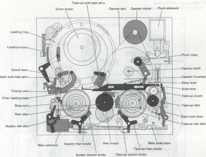
Fig. 2-1-9 Main parts location (Loading ring type)

Fig. 2-1-10 Mechanism mode (Loading ring type)
2) Loading arm 1 (LA-1) system
This is the basic loading arm system.
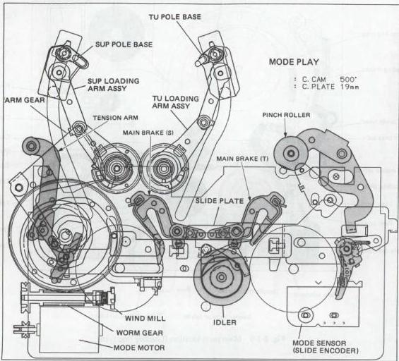
Fig. 2-1-11 Main parts location (LA-1 type)
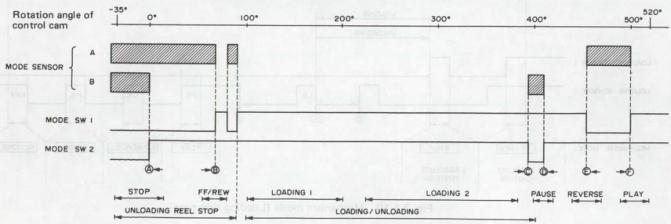
Fig. 2-1-12 Mechanism mode (LA-1 type)
| LOADING TYPE | MODEL NAME | |||
|---|---|---|---|---|
| LOADING ARM 1 | ||||
| :LA-1 | HR-D160EN | HR-D210 series | HR-D330 series | HR-D570U/U(C) |
| HR-D170 series | HR-D211EM | HR-D370 series | ||
| HR-D171A | HR-D217 series | HR-D430 series | ||
| HR-D180 series | HR-D230 series | HR-D470 series | ||
| HR-D190 series | HR-D310 series | HR-D530 series |
Table 2-1-4
3) Loading arm 2 (LA-2) system
This adds a new mechanical Slow/Still mode to the LA-1 type. Previously, during the shift from play to slow/still, the function was electrical and used a solenoid to operate the capstan brake. The LA-2 system adds a slow position to the slide encoder in place of the solenoid. The slide encoder detects the mode and the mechacon controls slow/still operation.
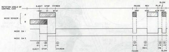
Fig. 2-1-13 Mechanism mode (LA-2 type)
| LOADING TYPE | MODEL NAME | |||
|---|---|---|---|---|
| LOADING ARM 2 | ||||
| :LA-2 | ||||
| (SLOW/STILL) | HR-D300 series | |||
| HR-D337MS |
Table 2-1-5
4) Half loading 1 (HL-1) system
The HL-1 system adds a half loading mechanism to the LA-1 type to allow high speed search (Index) operation that uses control coding. The half loading mechanism is comprised of half loading cam, slide cam plate, loading lever, connect plate, link lever assembly and half loading arm. The control plate and slide encoder also differ. When a cassette is inserted, the tape is extracted and brought into the half loading position. The supply and take-up loading arms do not load the tape during this operation.
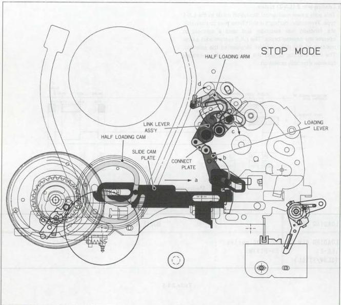
Fig. 2-1-14 Main parts location (HL-1 type)
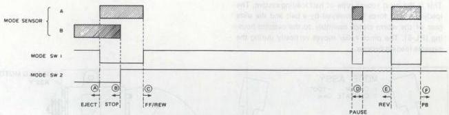
Fig. 2-1-15 Mechanism mode (HL-1 type)
| LOADING TYPE | MODEL NAME | |||
|---|---|---|---|---|
| HALF LOADING 1 | HR-D227 series | HR-D360U/U(C) | HR-D950 series | |
| :HL-1 | HR-D230U/U(C) | HR-D530U/U(C) | HR-S7000U/U(C) | |
| (INDEX) | HR-D237U/U(C) | HR-D630U/U(C) | HR-S8000U/U(C) |
5) Half loading 2 (HL-2) system
This adds the Slow/Still modes to the HL-1 type, in the same manner as LA-2.
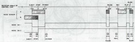
Fig. 2-1-16 Mechanism mode (HL-2 type)
Table 2-1-6
| LOADING TYPE | MODEL NAME | |||
|---|---|---|---|---|
| HALF LOADING 2 | HR-D400 series | HR-D750 series | ||
| :HL-2 | HR-D410 series | HR-S5000 series | ||
| (INDEX) | HR-D440 series | HR-S5500 series | ||
| (SLOW/STILL) | HR-D700 series | HR-S9000EG |
Table 2-1-7 6) Half loading 3 (HL-3) system
This is the most recent type of half loading system. The loading motor force is conveyed by a belt and the slide gear of the worm clutch assembly to the cassette housing (FL-5). The pinch roller moves vertically during the cassette loading process.
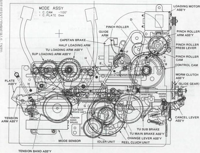
Fig. 2-1-17 Main parts location (HL-3 type)
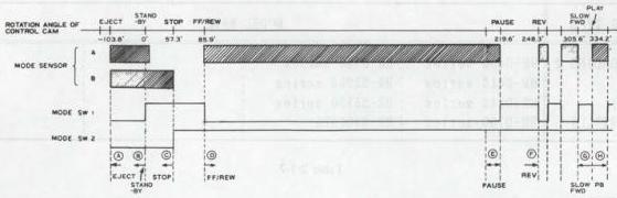
Fig. 2-1-18 Mechanism mode (HL-3 type)
| LOADING TYPE | MODEL NAME | ||
|---|---|---|---|
| HALF LOADING 3 | |||
| :HL-3 | |||
| (INDEX) | |||
| (SLOW FWD) | HR-D1830UM | ||
| HR-D4050U | |||
| HR-D520 series | |||
| HR-D522A (DK) | HR-D600 series | ||
| HR-D610 series | |||
| HR-D830 series |
Table 2-1-8
7) Full loading 1 (FULL-1) system
The full loading system was introduced with the editing model HR-S10000U. While similar to the LA-1 type, the control plate and slide encoder differ in order to speed mode shift during editing. The full loading mechanism also includes a slide plate and reverse tension arm. Tape loading begins as soon as a cassette is positioned, then the Stop mode is entered. This is the first model to use the slow reverse mode. During this mode, the reverse guide arm and tension brake function to stabilize reverse back tension.
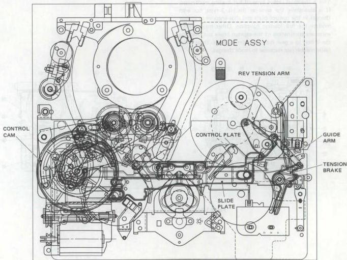
Fig. 2-1-19 Main parts location (FULL-1 type)
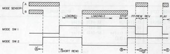
Fig. 2-1-20 Mechanism mode (FULL-1 type)
| LOADING TYPE | MODEL NAME | |||
|---|---|---|---|---|
| FULL LOADING 1 | ||||
| :FULL-1 | HR-S10000U |
Table 2-1-9
8) Full loading 2 (FULL-2) system
This is the most recent type of full loading mechanism. It is essentially the same as the HL-3 type, but with changes in the control plate and slide encoder to accommodate the full loading function. Other major differences are elimination of the capstan brake and changing the V-belt to a gear type belt (timing belt). These allow faster mechanism response to mode changes.
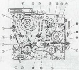
Fig. 2-1-21 Main parts location (FULL-2 type)
 | No. | Parts Name | No. | Parts Name | No. | Parts Name |
| --- | --- | --- | --- | --- | --- |
| 1 | Upper drum assy | 10 | Guide arm assy | 19 | Reel disk (take-up) |
| 2 | Full erase head | 11 | A/C head | 20 | Idler gear assy |
| 3 | End sensor | 12 | Capstan motor | 21 | Timing belt |
| 4 | Tension arm assy | 13 | Pinch roller arm assy | 22 | Take-up reel sensor (PHS1) |
| 5 | Tension band assy | 14 | Loading motor assy | 23 | Clutch assy |
| 6 | Lower drum motor assy | 15 | Pinch roller cam | 24 | Take-up loading arm assy |
| 7 | REC safety switch (S2) | 16 | Control cam | 25 | Supply loading arm assy |
| 8 | Brush assy | 17 | Loading belt | 26 | Plate assy |
| 9 | Half loading gear assy | 18 | LED holder (D1) | 27 | Slide switch (S3) |
| No. | Parts Name | No. | Parts Name | No. | Parts Name |
| --- | --- | --- | --- | --- | --- |
| 1 | Upper drum assy | 10 | Guide arm assy | 19 | Reel disk (take-up) |
| 2 | Full erase head | 11 | A/C head | 20 | Idler gear assy |
| 3 | End sensor | 12 | Capstan motor | 21 | Timing belt |
| 4 | Tension arm assy | 13 | Pinch roller arm assy | 22 | Take-up reel sensor (PHS1) |
| 5 | Tension band assy | 14 | Loading motor assy | 23 | Clutch assy |
| 6 | Lower drum motor assy | 15 | Pinch roller cam | 24 | Take-up loading arm assy |
| 7 | REC safety switch (S2) | 16 | Control cam | 25 | Supply loading arm assy |
| 8 | Brush assy | 17 | Loading belt | 26 | Plate assy |
| 9 | Half loading gear assy | 18 | LED holder (D1) | 27 | Slide switch (S3) |
Table 2-1-10 Main mechanical parts (FULL-2 type)
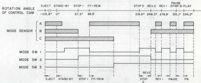
Fig. 2-1-22 Mechanism mode (FULL-2 type)
| LOADING TYPE | MODEL NAME | |||
|---|---|---|---|---|
| FULL LOADING 2 :FULL-2 | HR-D540 series | HR-D580 series | HR-S6600U | |
| HR-D550 series | HR-D660 series |
Table 2-1-11
9) Full loading 3 (FULL-3) system
This system was introduced with the HR-S1000U. The mechanism is the first to directly accommodate both full size VHS and compact size VHS-C cassettes. While basically the same as the FULL-2 (HL-3), there are considerable changes in mechanism parts. Table 2-1-12 com the the mechanism modes and sensors with the FULL-2 (S-VHS) type.
| FULL-3 type | FULL-2 type | ||
|---|---|---|---|
| MECHANISM | FULL/COMPACT SIZE | FULL SIZE | |
| MECHANISM MODE | 9 | 8 | |
| MOTOR | 4 | 3 | |
| SENSOR & SWITCH | CASS. S | 1 | 1 |
| ST. S | 1 | 1 | |
| END. S | 1 | 1 | |
| REC SAFE | 2 | 1 | |
| S CASS SW | 2 | 1 | |
| TRAY SW | 1 | — | |
| SIZE DET | 2 + 1 | — |
Table 2-1-12
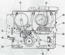
Fig. 2-1-23 Top view of main deck (FULL-3 type)
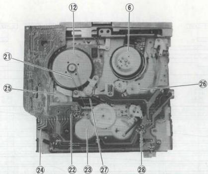
Fig. 2-1-24 Bottom view of main deck (FULL-3 type)
| No. | Parts Name | No. | Parts Name |
|---|---|---|---|
| 1 | Upper drum assy | 15 | Pinch roller cam |
| 2 | Full erase head | 16 | Half loading gear assy |
| 3 | End sensor | 17 | Belt (Mode motor) |
| 4 | Tension servo assy | 18 | LED holder assy |
| 5 | Tension band assy | 19 | Take-up reel disk |
| 6 | Lower drum motor assy | 20 | Gear assy |
| 7 | Rec switch assy | 21 | Timing belt |
| 8 | Brush assy | 22 | Reel sensor (Take up) |
| 9 | Guide arm gear assy | 23 | Gear unit assy |
| 10 | Half load arm assy | 24 | Slide switch |
| 11 | A/C head arm assy | 25 | Control cam |
| 12 | Capstan motor | 26 | Loading gear assy (Supply) |
| 13 | Pinch roller arm assy | 27 | Control plate assy |
| 14 | Mode motor assy | 28 | Reel sensor (Supply) |
Table 2-1-13 Main mechanical parts (FULL-3 type)
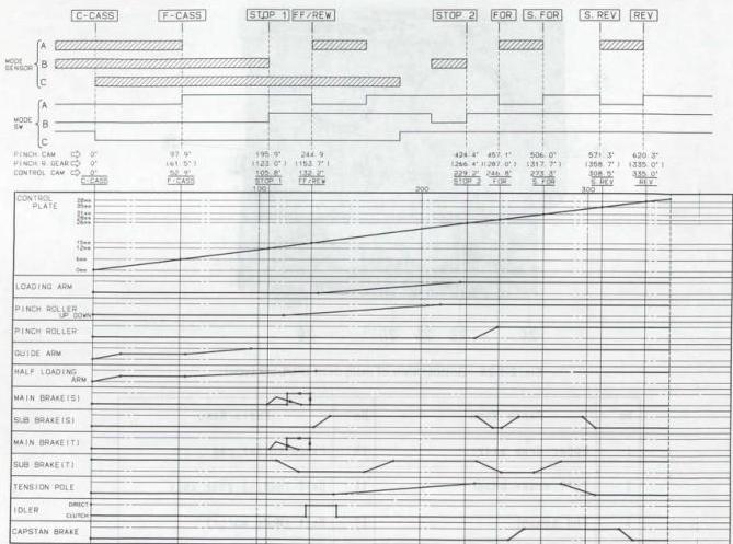
Fig. 2-1-25 Mechanism mode (FULL-3 type)
| LOADING TYPE | MODEL NAME | |||
|---|---|---|---|---|
| FULL LOADING 3 :FULL-3 | HR-SC1000U | HR-FC100 series |
Table 2-1-14
2.2 MECHANISM DESCRIPTION
2.2.1 Loading arm 1 mechanism (LA-1)
1. Function of main parts
1) Drum motor
The drum motor composed of a stator and rotor inside the lower drum drives the upper drum which is equipped with video heads.

Fig. 2-2-1 Drum motor chart
2) Capstan motor
The capstan motor rotates in the normal or reverse direction to more the tape.

Fig. 2-2-2 Capstan motor chart
3) Reel motor
The reel motor drives the reel idler by rotating in the normal or reverse direction. During tape running, this DC motor holds a clutch as well, for, it is pressed to contact both the supply and take-up reel disks to lighten a load caused by tape running.
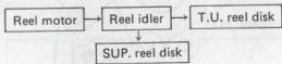
Fig. 2-2-3 Reel motor chart
4) Mode control motor
This transmits motive power generated by its rotation in the normal or reverse direction to the worm assembly through the mode control belt. Then the power is transmitted to the control cam gearing with the worm assembly. As the control cam turns, the control plate is moved from left to right along the groove of the cam's front side by the motive power. At the same time, the power is also transmitted to the arm gear along the groove of the cam's back side to move the loading arm for loading and unloading.
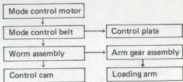
Fig. 2-2-4 Mode control motor chart
2. Mechanism mode
The mechanism mode is classified into five basic modes of PLAY, REV, SEARCH, PAUSE, FF/REW and STOP, and three other modes of ASSEMBLY, LOADING 1 and 2. The Assembly mode is provided for assembling the mechanism, and Loading-1 & -2 modes are for switch-over of the Stop and Play modes.
The following explanations confirm the condition of the deck mechanism in each mode in practice.
1) Assembly mode
- This mode is provided for assembling the cam gear and arm gear.
- The main brakes are pressed to contact with the TU reel disk and SUP. reel disk in an over-load condition.
- The sub-brakes of the TU and SUP. reel disks are pressed to contact with them.
- The loading arm is positioned at the limit in the direction of unloading, and holes of the TU and SUP. arm gears are horizontally positioned when they are geared with each other.
- The reel idler is at the neutral position.
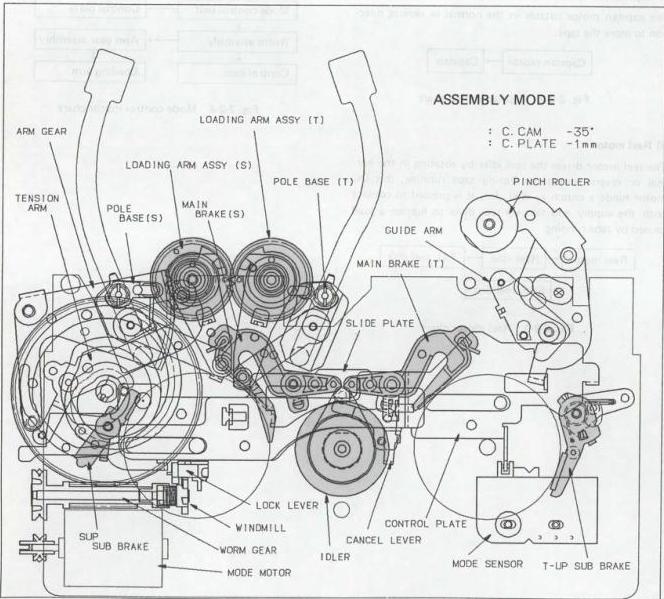
Fig. 2-2-5 Assembly mode
(2) Stop mode
In this mode, the mechanism condition is the same as in the assembly mode except that the main brake's overload is released and the control plate is positioned slightly to the right.
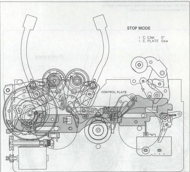
Fig. 2-2-6 Stop mode
3) FF/REW mode
- The main brakes are released.
- The sub-brakes are pressed to contact with the reel disks to prevent the tape from slackening and being wound irregularly.
- The loading arm is positioned the same as in the Stop mode.
- The reel idler is pressed to the reel disk by rotation of the reel motor and it turns the reel disk.
- When the STOP button is pressed and the main brakes work, the reel motor does not stop immediately and the idler becomes positioned at the neutral.
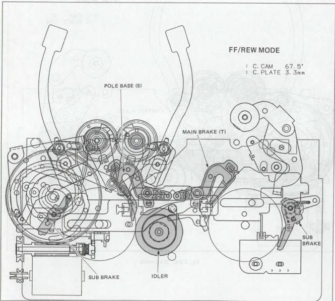
Fig. 2-2-7 FF/REW mode
4) L1 (Loading-1) mode
- The main brake of the SUP. side is released, but the main brake of the TU side is pressed to the TU reel disk to be engaged in braking.
- The sub-brakes are pressed to reel disks to prevent the tape from slackening.
- The loading arm comes in the loading mode and is sitting at the position where the tape is slightly pulled out of the cassette housing.
- In loading, the reel idler is situated at the neutral and the tape is forwarded only from the supply side. In unloading, the reel idler is pressed to contact with the supply reel disk for winding the tape.
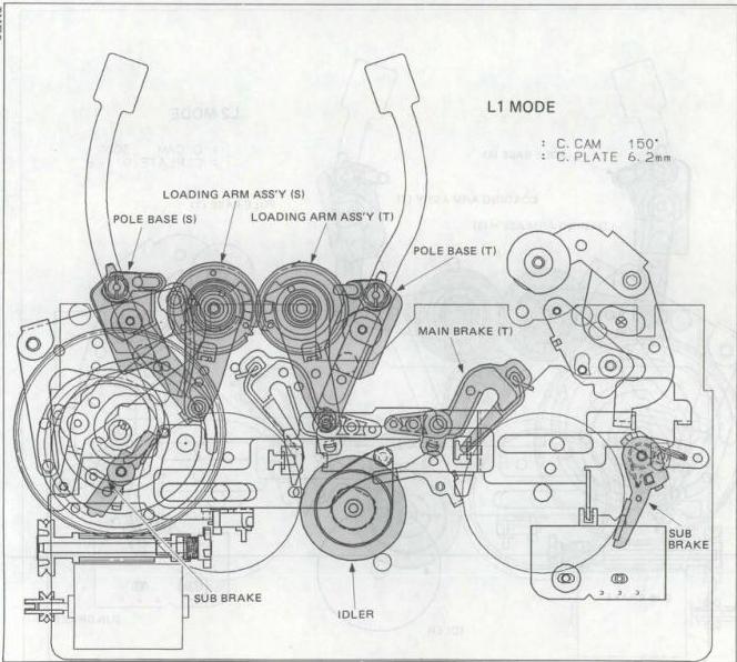
Fig. 2-2-8 L1 (Loading-1) mode
5) L2 (Loading-2) mode
(1) The main brakes are released. However, with the sub-brake at the point of the SUP, the main brake is engaged. This sub-brake, lying over the tension band, is pressed to contact with the supply reel disk in order to tension the tape at a certain force for controlling the amount of pulled tape.
(2) The sub-brake is pressed to the reel disk.
(3) The loading arm is coming in the loading mode and situated nearly at the mid-point of the loading process.
(4) In loading, the reel idler is sitting at the neutral position. Contrary to the L1 mode in which the tape is only pulled out of the supply side, in the L2 mode the tape is pulled out of the take-up side, too. This decreases scanning error.
(5) In unloading, the reel idler is pressed to the supply reel disk to wind the tape.
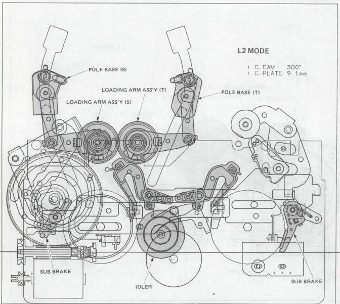
Fig. 2-2-9 L2 (Loading-2) mode
6) Pause mode
- The main brakes are disengaged.
- The sub-brakes are disengaged, too.
- The loading arm is situated at the position that loading is completed, and the tape entwines around the drum.
- The pinch roller is disconnected from the capstan.
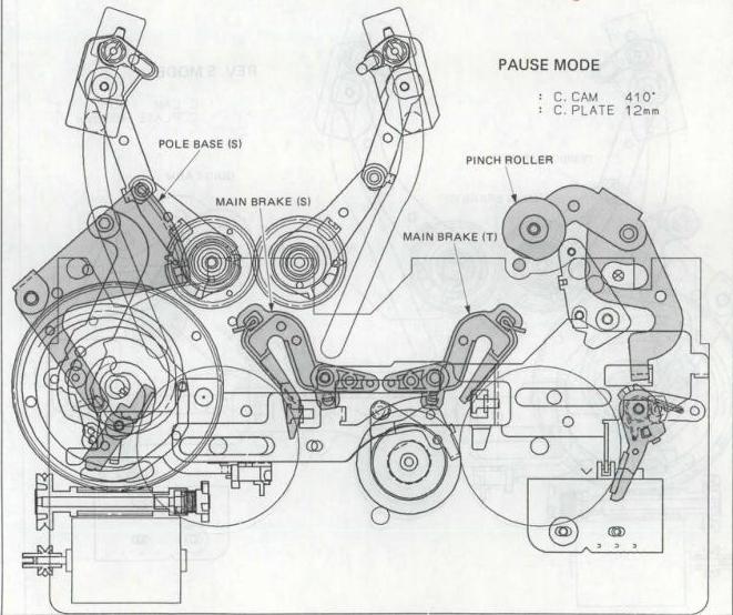
Fig. 2-2-10 Pause mode
7) REV Search mode
- The main brakes are disengaged.
- The SUP, sub-brake is released to remove a load on the tape in winding, while the TU sub-brake is pressed to the take-up reel disk for applying back-tension to the tape.
- The loading arm is sitting at the loading end position, and, the tape being contacted with the drum passes between the capstan and the pinch roller, which are pressed to contact with each other.
- The reel idler has been moved to the supply side to wind the tape.
- In order to forward the tape smoothly without slackening, the tension arm is moved to the outside of the deck to take a load on the reel disk.
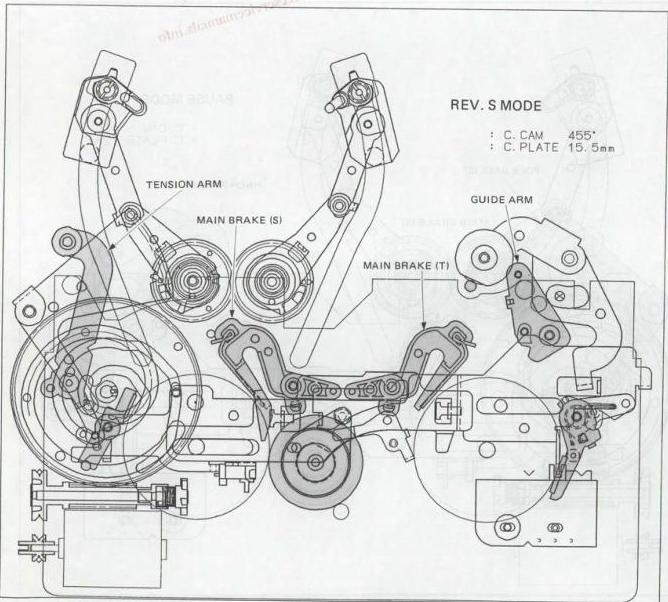
Fig. 2-2-11 Search REW mode
(1) Play mode
- The main brakes are disengaged.
- The sub-brakes are also released to remove a load on the tape for smooth running.
- The loading arm is sitting at the loading end position. The pinch roller and the capstan are pressed to contact with each other.
- The reel idler is moved to the take-up side to wind the tape forwarded by the capstan.
- The tension arm contacts the tape to produce a back tension on it by this braking so that tension of the tape becomes constant during entwining around the drum.
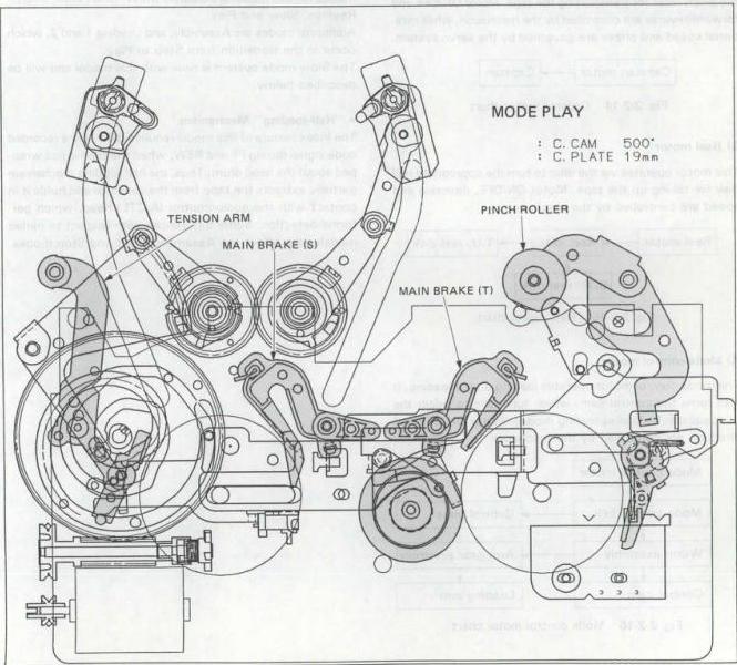
Fig. 2-2-12 Play mode
2.2.2 Half loading 1 mechanism (HL-1)
1. Functions of main parts
1) Drum motor
The direct-drive (DD) drum motor turns the upper drum, which contains the rotary heads. Motor ON/OFF is controlled by the mechacon (mechanism control system), while rotational speed and phase are governed by the servo system.
Drum motor → Rotary video heads
Fig. 2-2-13 Drum motor chart
2) Capstan motor
This is also a DD type motor and functions together with the pinch roller for transporting the tape. Motor ON/OFF and forward/reverse are controlled by the mechacon, while rotational speed and phase are governed by the servo system.
Capstan motor → Capstan
Fig. 2-2-14 Capstan motor chart
3) Reel motor
This motor operates via the idler to turn the appropriate reel disk for taking up the tape. Motor ON/OFF, direction and speed are controlled by the mechacon.
Reel motor → Reel idler → T.U. reel disk
↓
SUP. reel disk
Fig. 2-2-15 Reel motor chart
4) Mode control motor
The mode control motor operates loading and unloading. It also turns the control cam, which functions to select the principal mechanical operating modes. Motor ON/OFF and direction are controlled by the mechacon.
Mode control motor
↓
Mode control belt → Control plate
↓
Worm assembly → Arm gear assembly
↓
Control cam → Loading arm
Fig. 2-2-16 Mode control motor chart
5) Cassette motor
This motor assists cassette insertion and removal. Operation and direction are controlled by the mechacon.
2. Mechanism modes
It is suggested to outline the modes in different colors.
- Mechanism function in each mode
The mode sensors control the operations of the mechanism components for each mode. The six basic mechanism modes for this model are Stop, FF/REW, REC Pause, Search Reverse, Slow and Play.
Additional modes are Assembly, and Loading 1 and 2, which occur in the transition from Stop to Play.
The Slow mode system is new with this model and will be described below.
- “Half-loading” Mechanism
The Index feature of this model requires detecting a recorded code signal during FF and REW, when the tape is not wrapped about the head drum. Thus, the half-loading mechanism partially extracts the tape from the cassette and holds it in contact with the audio/control (A/CTL) head, which performs detection. Some differences with respect to earlier models also affect the Assembly, Eject and Stop modes.
1) Half-loading mechanism
(1) The half-loading mechanism is introduced with this model. In the Stop mode, the tape is partially extracted from the cassette and brought into contact with the A/CTL head. This allows detecting the Index code during high speed search operation.
(2) The main components of the half-loading mechanism are as follows.
Half-loading cam: The lower groove of the half-loading cam shifts the slide cam plate horizontally to move the half-loading arm.
Slide cam plate: This is separate from the existing slide plate and was added specifically for the half-loading function.
Loading lever: The slide cam plate hole and loading lever shaft convert the horizontal motion of the slide cam plate into rotary motion about the slide cam plate shaft.
Connect plate and link lever assembly: Transfer the rotary motion of the loading lever to the half-loading arm.
2) Assembly mode
(1) This is the state at which the mechanism is assembled at the factory. It can be achieved only with power OFF. To set this mode, turn off main power and position the components manually.
(2) Assembling and adjusting the relationships of the half-loading components are also performed in the Assembly mode.
(3) To set the half-loading cam, align hole “a” of the half-loading cam with the hole of the cam gear and the reference hole of the deck.
(4) In this state, engage pin “A” of the slide cam plate with the groove of the half-loading cam. This adjusts the slide cam plate relationship.
(5) Assemble the loading lever by aligning hole “b” with the reference hole of the deck.
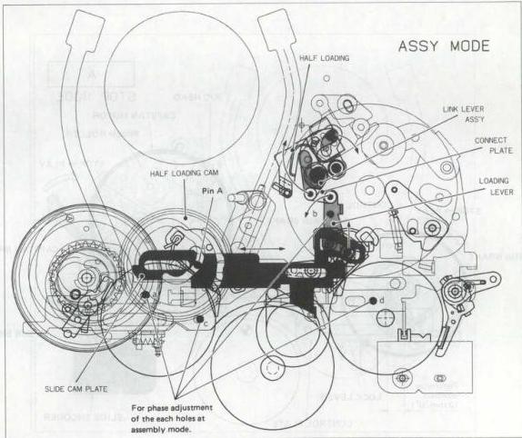
Fig. 2-2-17 Assembly mode
2.2.3 Loading ring 2 mechanism (LA-2)
(Half loading 2 mechanism : HL-2)
1. Slow/Still mode mechanism
The mechanism for the Slow mode is newly introduced with this model. In previous models, during the shift from Play to Slow/Still, the capstan motor was stopped electrically using a solenoid and the capstan brake engaged.
In the new series, the Slow/Still mode is operated mechanically. The solenoid is deleted and the mode setting of the slide encoder is detected.
Except for the changes locations, other functions (Eject, Assembly, FF/REW, Loading 1 and 2, Search Reverse and Play modes) are the same as previous models.
1. Slow/Still mode
For the Slow/Still mode, the mechacon instructs the mode control motor. The control cam and control plate shift to apply the capstan brake. At the same time, the slide encoder detects the mode.
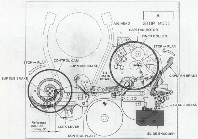
Fig. 2-2-18 Stop mode
2.2.4 Half loading 3 mechanism (HL-3)
1. Overflow
The following three motors are used in the new mechanism.
- Drum motor
- Capstan motor
- Loading motor
These motors are controlled either by the mechanism controller or the servo circuit.
1) Drum motor (direct drive)
This motor drives the upper drum where the rotary head is mounted. The motor is turned on and off by the mechanism controller and the speed and phase are servo controlled.
2) Capstan motor (direct drive)
When loading is completed, this motor works together with the pinch roller to transport the tape. This motor also drives the reel disk via a belt for tape takeup.
The motor is turned on and off, and forward and reverse operation is switched by the mechanism controller. The speed and phase are servo controlled.
3) Loading motor (belt drive)
This motor drives the control cam, switches the loading/unloading operations and also the mechanism modes. The power from this motor is transmitted to the cassette housing via the worm pulley slide gear to load and unload cassettes.
The motor is turned on and off, and forward and reverse operation is switched by the mechanism controller.
2. Mechanism modes
While reading, identify the various modes by color and then confirm.
- Model operation
The mode sensors control the operation of each component for each mode. The 8 basic mechanism modes are eject, standby, stop, FF/REW, pause, reverse, slow forward and play.
- New components
1) Worm clutch assembly
The worm clutch assembly consists of the pulley, slide gear, worm gear and windmill.
(1) The slide gear transmits the power from the loading motor to the cassette housing. This gear is turned on and off by the cancel lever to start or stop the transmission of motor power to the cassette housing.
(2) The worm gear transmits the power from the loading motor to the control cam via the worm.
(3) The windmill is rotated by the loading motor and releases the slide plate lock by operating the lock lever.
2) Control cam
The power from the loading motor is transmitted to the control cam by the worm gear. The control cam then controls the half-loading arm/guide arm, pinch roller and plate assembly.
3) Half-loading arm/guide arm
(1) The half-loading arm is rotated clockwise by the counterclockwise rotation of the control cam to load the video tape.
(2) The guide arm is rotated counterclockwise by the clockwise rotation of the half-loading arm to load the video tape.
4) Pinch roller
The pinch roller is part of the pinch roller arm assembly. This pinch roller arm assembly is operated by the pinch roller press lever and pinch roller cam.
(1) The pinch roller cam consists of the gear which meshes with the control cam and the worm slot which moves the pinch roller press lever up and down.
(2) The pinch roller press lever moves up and down along the worm slot in the pinch roller cam to regulate the operation of the pinch roller arm assembly. After dropping down, the pin of the pinch roller lever enters the slot in the control cam, is pushed along the control cam slot by the counterclockwise rotation of the control cam and presses the pinch roller against the capstan.
5) Plate assembly
The plate assembly consists of the control plate, slide plate and lock lever and controls the loading arm assembly, tension arm, main brake, tension band brake, takeup subbrake, cancel lever assembly and change lever assembly.
(1) The control plate converts the rotary motion of the control cam to reciprocal lateral motion by means of the linear rack gear. All parts except the loading arm assembly are controlled by this reciprocal lateral motion. The gear of the loading arm assembly meshes with the other linear rack gear of the control plate and converts the reciprocal lateral motion back into rotary motion.
6) Assembly mode (EJECT mode)
(1) The pinch roller cam, half-loading gear assembly and guide arm assembly are assembled and the phases are adjusted with the “eject mode” as the basic position.
(2) Assemble so that the phases of hold A on the pinch roller cam and hole B on the control cam are aligned with the deck reference hole. Also set so that the phases of hole C in the control cam and part B on the pinch roller cam are matched.
(3) Assemble so that the phases of hole E in the half-loading gear and the deck reference hole are matched. Next, assemble so that the phases of hole F in the guide arm assembly and the deck reference hole are matched.
(4) To adjust the plate assembly phase, operate the plate assembly, match hole G in the slide plate with the upper and lower control plates, and align hole H with the deck reference hole. This adjusts the phase of the plate assembly.
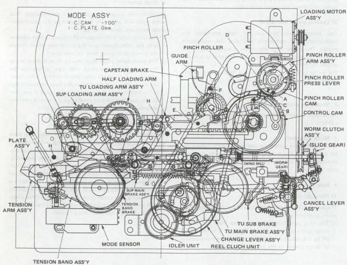
Fig. 2-2-19 Assembly mode
2.2.5 Full loading 1 mechanism (FULL-1)
1. Functions of main parts
1) Drum motor
The direct-drive (DD) drum motor turns the upper drum, which contains the rotary heads. Motor ON/OFF is controlled by the mechacon (mechanism control system), while rotational speed and phase are governed by the servo system.
Drum motor → Rotary video heads
Fig. 2-2-20 Drum motor chart
2) Capstan motor
This is also a DD type motor and functions together with the pinch roller for transporting the tape. Motor ON/OFF and forward/reverse are controlled by the mechacon, while rotational speed and phase are governed by the servo system.
Capstan motor → Capstan
Fig. 2-2-21 Capstan motor chart
3) Reel motor
This motor operates via the idler to turn the appropriate reel disk for taking up the tape. Motor ON/OFF, direction and speed are controlled by the mechacon.
Reel motor → Reel idler → T.U. reel disk
↓
SUP. reel disk
Fig. 2-2-22 Reel motor chart
4) Mode control motor
The mode control motor operates loading and unloading. It also turns the control cam, which functions to select the principal mechanical operating modes. Motor ON/OFF and direction are controlled by the mechacon.
Mode control motor ↓
Mode control belt → Control plate
↓
Worm assembly → Arm gear assembly
↓
Control cam → Loading arm
Fig. 2-2-23 Mode control motor chart
5) Cassette motor
This motor assists cassette insertion and removal. Operation and direction are controlled by the mechacon.
2. Mechanism modes
For each mode of the following, it is suggested to distinguish by using different colors.
- Mechanism function in each mode
The mechanism function and practical operation in each mode (operating condition of the mechanism) are under the management of the mode sensor.
Besides the six basic mechanism modes of Eject, Short REW, Stop, FF/REW, Reverse and Play, this model has other three modes of Loading-1 and Loading-2 which are operated in the course of the mode shift from Eject to Stop, and Assembly mode that is used to assemble the deck.
- New mechanism of HR-S10000 NTSC
1) Full-loading mechanism
This mechanism functions to start the Loading operation with finish of the cassette loading and to set the mode to Stop after the Loading finishes.
The characteristic of this mechanism has no need of the Half-loading mechanism employed in models after HR-D530U since the loaded tape always contacts the A/C head. In addition, it makes the operational speed of the mechanism faster in mode shifting from Stop to Play and from Play to FF/REW and to Play again.
2) REV tension arm mechanism
This model employs the Slow Reverse function first to be used as a full-scale editing machine with a JOG/SHUTTLE dial.
For stable tape running in the Slow Reverse operation, the guide arm and the tension brake of the REV tension arm mechanism are interlocked to keep a constant reverse back tension.
1) Operations of full-loading mechanism and REV tension arm
(1) The HR-S10000 NTSC is the first model employing the full-loading mechanism, which enables the deck to be used as a full-scale editing machine by the function not only to gather speed of mode shifting but also to make audio monitoring possible. For realizing this function, the deck starts full-loading operation and enters Stop mode to contact the tape with the A/C head immediately after the deck is loaded with a cassette.
The REV tension arm interlocks the tension brake and the guide arm with each other. During tape running in the Slow Reverse operation, the tension brake presses on the take-up reel disk to prevent the tape from slackening and, at the same time, the guide arm interlocked with the tension brake activates the REV tension arm to maintain an even tape tension in counter-running of the tape.
(2) Component parts related to the new mechanism
- Control cam, control plate, slide plate
The groove on the underside of the control cam moves the control plate in order to operate and shift the main brake, sub brake, tension brake and pinch roller arm.
In addition to the control plate as in those used currently, this model has the slide plate, which is moved right and left by the ridge of the lower side of the control cam in order to put the main brake into action in the FF/REW mode.
- REV tension arm, guide arm, tension brake
The tension brake and the REV tension arm are operated by the movement of the control plate, and the tension brake and the REV tension arm are interlocked by the guide arm to stabilize tape running in the reverse direction.
The following description about the mechanism centers operations of the full-loading mechanism and the REV tension arm.
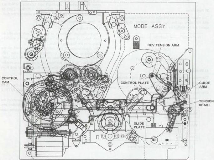
Fig. 2-2-24 Main component parts of the new mechanism
2) Assembly mode
- The assembly mode is the standard mode to assemble the mechanism at the factory, and it cannot be set with the power on. To set the mechanism to this mode, make sure to do it manually with the power off.
- To assemble the component parts of the full-loading mechanism and to adjust its phase, set the mechanism to the Assembly mode.
- Phase adjustment of the control cam can be performed by setting the hole \(\boxed{\text{a}}\) of the control cam so as to coincide its phase with that of the arm gear's hole and of the control cam bracket's reference hole.
- For phase adjustment of the control plate and the slide plate, adjust the phase of the upper hole \(\boxed{\text{b}}\) of the control phase by the reference hole of the deck. In this state, fit the pin \(\boxed{\text{A}}\) of the control plate in the groove of the control cam.
- In the Assembly mode and Eject mode, the reel idler is controlled by the control plate so that it stands neutrally. In other modes, it is controlled by voltage of the reel motor.
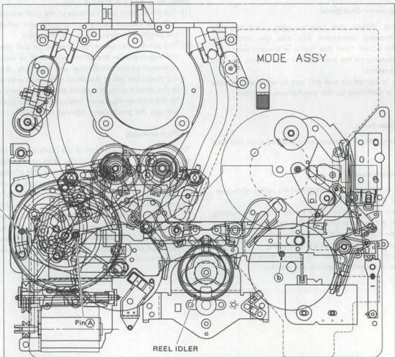
Fig. 2-2-25 Mechanism condition in Assembly mode
2.2.6 Full loading 2 mechanism (FULL-2)
- Overview
The following three motors are used in the new mechanism. - Drum motor - Capstan motor - Loading motor
These motors are controlled either by the mechanism controller or the servo circuit.
1) Drum motor (direct drive)
This motor drives the upper drum where the rotary head is mounted. The motor is turned on and off by the mechanism controller and the speed and phase are servo controlled.
2) Capstan motor (direct drive)
When loading is completed, this motor works together with the pinch roller to transport the tape. This motor also drives the reel disk via a belt for tape takeup.
The motor is turned on and off, and forward and reverse operation is switched by the mechanism controller. The speed and phase are servo controlled.
3) Loading motor (belt drive)
This motor drives the control cam, switches the loading/unloading operations and also the mechanism modes. The power from this motor is transmitted to the cassette housing via the worm pulley slide gear to load and unload cassettes.
The motor is turned on and off, and forward and reverse operation is switched by the mechanism controller.
- Mechanism parts
While reading, identify the various modes by color and then confirm.
1) Worm clutch assembly
The worm clutch assembly consists of the pulley, slide gear, worm gear and windmill. (1) The slide gear transmits the power from the loading motor to the cassette housing. This gear is turned on and off by the cancel lever to start or stop the transmission of motor power to the cassette housing. (2) The worm gear transmits the power from the loading motor to the control cam via the worm.
(3) The windmill is rotated by the loading motor and releases the slide plate lock by operating the lock lever.
2) Control cam
The power from the loading motor is transmitted to the control cam by the worm gear. The control cam then controls the half-loading arm/guide arm, pinch roller and plate assembly.
3) Half-loading arm/guide arm
(1) The half-loading arm is rotated clockwise by the counterclockwise rotation of the control cam to load the video tape. (2) The guide arm is rotated counterclockwise by the clockwise rotation of the half-loading arm to load the video tape.
4) Pinch roller
The pinch roller is part of the pinch roller arm assembly. This pinch roller arm assembly is operated by the pinch roller press lever and pinch roller cam. (1) The pinch roller cam consists of the gear which meshes with the control cam and the worm slot which moves the pinch roller press lever up and down. (2) The pinch roller press lever moves up and down along the worm slot in the pinch roller cam to regulate the operation of the pinch roller arm assembly. After dropping down, the pin of the pinch roller lever enters the slot in the control cam, is pushed along the control cam slot by the counterclockwise rotation of the control cam and presses the pinch roller against the capstan.
5) Plate assembly
The plate assembly consists of the control plate, slide plate and lock lever and controls the loading arm assembly, tension arm, main brake, tension band brake, takeup subbrake, cancel lever assembly and change lever assembly. (1) The control plate converts the rotary motion of the control cam to reciprocal lateral motion by means of the linear rack gear. All parts except the loading arm assembly are controlled by this reciprocal lateral motion. The gear of the loading arm assembly meshes with the other linear rack gear of the control plate and converts the reciprocal lateral motion back into rotary motion.
3. Outline
A full loading system is used for the mechanism of this model. The system features fast response when changing mechanism modes.
In previous systems, several seconds were needed in the mode shift from Stop to Play. But in the full loading system, a playback picture output is obtained in about 1 second. As can be noted from the figure, the full loading mechanism is essentially the same as the previously introduced "half loading" mechanism. The differing points are compared in the following pages.
1) Comparisons
(1) Slide encoder (mode switch)
Two switches were used for detecting mechanism modes in previous models. A third switch is added to this model for detecting half loading and full loading Stop modes.
(2) Removal of Capstan Brake
The capstan brake was removed and a tension brake was added by changing the conventional V-belt into a gear belt (timing belt). This is to speedup the mode shift response (for example, from S-REW to S-FF).
The revolution of the capstan motor is transferred by the timing belt to the center pulley assembly. This timing belt's gear meshes with the gear mounted on the capstan motor, and is also designed to mesh with the center pulley's gear, so the capstan motor's revolution will be transmitted immediately and accurately to the center pulley without slipping and without any loss of revolution. The timing belt's tension is adjusted with the tension pulley.
4. Main mechanism parts
1) Full loading
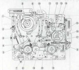
Fig. 2-2-26 Top view of main-deck
(3) Change to Two-Stage Reel Clutch (Idler Gear)
Changing to the two-stage gear ratio enables high-speed winding. However, when the load is large at time of starting and at the tape end, the capstan motor's drive voltage is controlled to alleviate the impact.
(4) Strengthening of Pinch Roller Arm and Changing of Pinch Roller Press Lever Shape
The pinch roller will be actuated frequently to enable rapid shifting to the modes of the respective mechanisms, so the pinch roller arm was strengthened and the shape of the pinch roller press lever changed.
(5) Change of Control Cam Shape
The shape of the control cam's groves was changed to enable the pinch roller to be switched to OFF for a short period of time during the PAUSE mode (when switching from S-FF to S-REV).
(6) Addition of SUP-REEL SENSOR
This is to enable display (computing) of remaining tape volume.
(7) Addition of Stabilizer on Impedance Roller
This has been added to suppress jittering.
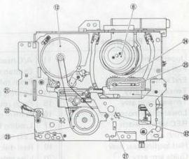
Fig. 2-2-27 Bottom view of main-deck | No. | Parts Name | No. | Parts Name | No. | Parts Name | | --- | --- | --- | --- | --- | --- | | 1 | Upper drum assy | 11 | A/C head | 21 | Timing belt | | 2 | Full erase head | 12 | Capstan motor | 22 | Take-up reel sensor | | 3 | End sensor | 13 | Pinch roller arm assy | 23 | Clutch assy | | 4 | Tension arm assy | 14 | Loading motor assy | 24 | Take-up loading arm assy | | 5 | Tension band assy | 15 | Pinch roller cam | 25 | Supply loading arm assy | | 6 | Lower drum motor assy | 16 | Control cam | 26 | Plate assy | | 7 | REC safety switch | 17 | Loading belt | 27 | Slide switch | | 8 | Brush assy | 18 | LED holder | 31 | Reel disk (Supply) | | 9 | Half loading gear assy | 19 | Reel disk (Take-up) | 32 | Supply reel sensor | | 10 | Guide arm assy | 20 | Idler gear assy | | |
Table 2-2-1 Main mechanical parts (Full loading)
2) Half loading
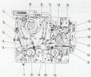
Fig. 2-2-28 Top view of main-deck
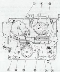
Fig. 2-2-29 Bottom view of main-deck
| No. | Parts Name | No. | Parts Name | No. | Parts Name |
|---|---|---|---|---|---|
| 1 | Upper drum assy | 11 | A/C head | 21 | Reel belt |
| 2 | Full erase head | 12 | Capstan motor | 22 | Take-up reel sensor |
| 3 | End sensor | 13 | Pinch roller arm assy | 23 | Clutch assy |
| 4 | Tension arm assy | 14 | Loading motor assy | 24 | Take-up loading arm assy |
| 5 | Tension band assy | 15 | Pinch roller cam | 25 | Supply loading arm assy |
| 6 | Lower drum motor assy | 16 | Control cam | 26 | Plate assy |
| 7 | REC safety switch | 17 | Loading belt | 27 | Slide switch |
| 8 | Brush assy | 18 | LED holder | 31 | Reel disk (Supply) |
| 9 | Half loading gear assy | 19 | Reel disk (Take-up) | ||
| 10 | Guide arm assy | 20 | Idler gear assy |
Table 2-2-2 Main mechanical parts (Half loading)
2.2.7 Tray loading mechanism
1. Outline
Four motors are used in this model: drum, capstan, loading and cassette. These are controlled by the syscon (system control) and servo circuits.
1) Drum motor (direct drive)
This motor turns the upper drum which contains the rotary heads. The syscon circuit controls motor on/off, while speed and phase are controlled by the servo circuit.
2) Capstan motor (direct drive)
Functions with the pinch roller to transport the tape. The motor turns the reel disk through a belt for tape take-up.
The syscon circuit controls motor on/off, while speed and phase are controlled by the servo circuit.
3) Loading motor
This motor turns the control cam for loading and unloading, and setting the mechanism modes. The syscon circuit controls motor on/off and forward/reverse.
4) Cassette motor (belt drive)
This motor functions for inserting and ejecting the cassette. The syscon circuit controls motor on/off and forward/reverse. As this model uses a cassette tray, the tray and cassette door are operated by belt drive.
The loading and cassette motors are controlled separately by a single IC.
2. Mechanism modes
There are 9 mechanism modes: Eject (full and C cassette), Stop 1, FF/REW, Stop 2, Forward, Forward Slow/Still, Reverse Slow/Still and Reverse. Mode shift is controlled by the syscon circuit according to the mode sensor (3 position).
| HR-SC1000 U | HR-S6600 U | ||
|---|---|---|---|
| CASSETTE HOUSING | CASSETTE TRAY | – | |
| MECHANISM | FULL/COMPACT SIZE | FULL SIZE | |
| MECHANISM MODE | 9 | 8 | |
| MOTOR | 4 | 3 | |
| SENSOR & SWITCH | CASS.S | 1 | 1 |
| ST.S | 1 | 1 | |
| END.S | 1 | 1 | |
| REC SAFE | 2 | 1 | |
| S CASS.SW | 2 | 1 | |
| TRAY SW | 1 | – | |
| SIZE DET | 2 + 1 | – |
Fig. 2-2-30
3. Switches and sensors
The syscon detects the set mode from the states of the switches and sensors.
1) REC safety switches
These detect presence of the cassette erase protector tab. One switch each is provided for full size and C cassettes, however both use the same detector port.
When the erase protector tab is absent (switch is off), REC and REC Pause are inhibited. If the Timer button is pressed, the cassette is ejected. (However, the Timer button is inoperative if the mainframe clock has not been set.)
2) VHS cassette detectors
Differentiate between S-VHS and VHS cassettes. One switch each is provided for full size and C cassettes, however both use the same detector port.
3) Tray switch
Detects status of the cassette tray. “High” when the tray is retracted within the mainframe.
4) Cassette switches
These detect the cassette size. Two series connected switches detect full size and a third switch detects compact size.
5) Cassette sensor
This detects the cassette housing status. See Section 2.4.
6) Start sensor
Detects the leader tape at the beginning of the cassette. If the Stop mode, the tape is transported in the forward direction until the leader tape passes the sensor.
7) End sensor
Detects the trailer tape at the end of the cassette. In other than Stop, Timer REC and Instant REC, the REW mode is entered automatically when the trailer tape is detected. If Timer or Instant REC, the tape is unloaded and the power cut off.
8) Reel sensors
These detect take-up and supply reel disk rotation. The reel frequency generator is used to computer tape remaining.
9) Mode switches
Switches A, B and C detect the mechanism modes.
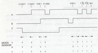
Fig. 2-2-31
In previous models, the mode switch data went directly to the syscon CPU. In this mode, the data are first entered in IC1, then sent periodically to the syscon CPU.
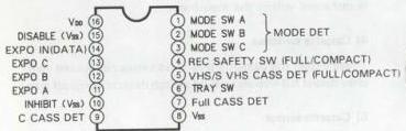
Fig. 2-2-32
IC1 Pin Function
10) Start and end sensors
These sensors also detect the cassette housing status. At completion of loading, if both sensors are activated, tape breakage is interpreted and the cassette is ejected.
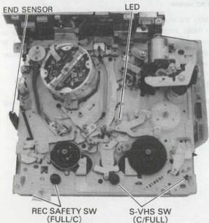
Fig. 2-2-33
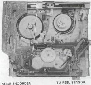
Fig. 2-2-34
SUP REEL SENSOR
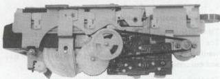
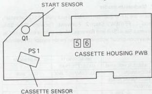
Fig. 2-2-35
START SENSOR
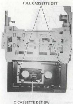
Fig. 2-2-36
2.3 CASSETTE HOUSING DESCRIPTION
2.3.1 Front loading type (FL-1)
1. Cassette loading
A cassette can be loaded into the cassette housing by opening the cassette door and inserting a cassette. Pushing a cassette into the housing pushes the slider assembly, and at the same time, the Main gear (R) connected with the slider assembly rotates. When the Main gear (R) rotates, the cassette sensor turns off and the cassette motor starts rotation.
As the Main gear (R), Idler gear, and Idler pulley gear are engaged in series, motive power of the cassette motor is to one to move the projection of the slider assembly, and the cassette holder assembly comes down along the groove to finish cassette loading.
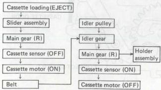
Fig. 2-3-1 Cassette loading chart
Loading
2. Cassette unloading
When the EJECT switch is pressed, the mechanism enters REW mode for several seconds, and then, the cassette motor starts rotating and its motive power is transmitted from the Idler pulley opposite to the loading mode. This power finally moves the cassette holder assembly upward. When unloading finishes, the cassette sensor is turned on by the drive gear to stop the cassette motor.
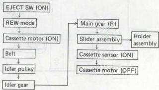
Fig. 2-3-2 Cassette unloading chart
Unloading
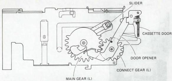
Fig. 2-3-3 Cassette housing (L) 1
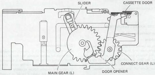
Fig. 2-3-4 Cassette housing (L) 2
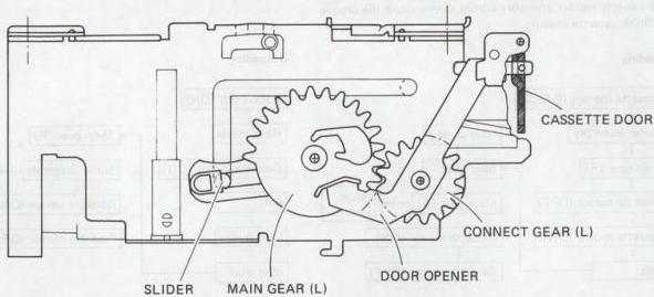
Fig. 2-3-5 Cassette housing (L) 3
• CASSETTE MOTOR • BELT • IDLER PULLEY
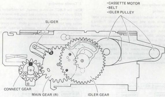
Fig. 2-3-6 Cassette housing (R) 1
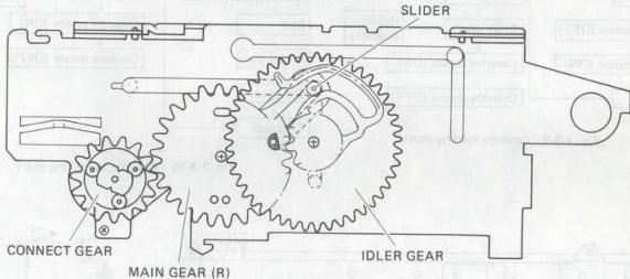
Fig. 2-3-7 Cassette housing (R) 2
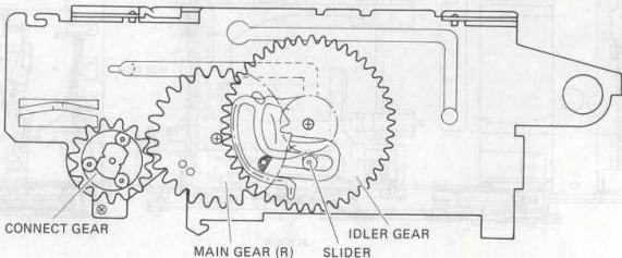
Fig. 2-3-8 Cassette housing (R) 3
2.3.2 Side loading type (SL-1)
1. Cassette loading
A cassette can be loaded into the cassette housing by opening the cassette door and inserting a cassette. Pushing a cassette into the housing pushes the slider assembly, and at the same time, the drive gear connected with the slider assembly rotates. When the drive gear rotates, the cassette sensor turns off and the cassette motor starts rotation.
As the drive gear, cam gear, shift gear and pulley gear are engaged in series, motive power of the cassette motor is to one to move the projection of the slider assembly, and the cassette holder assembly comes down along the groove to finish cassette loading.
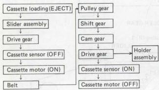
Fig. 2-3-9 Cassette loading chart
Loading
2. Cassette unloading
When the EJECT switch is pressed, the mechanism enters REW mode for several seconds, and then, the cassette motor starts rotating and its motive power is transmitted from the pulley gear opposite to the loading mode. This power finally moves the cassette holder assembly upward. When unloading finishes, the cassette sensor is turned on by the drive gear to stop the cassette motor.
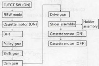
Fig. 2-3-10 Cassette unloading chart
Unloading
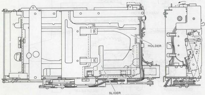
Fig. 2-3-11 Cassette housing - 1 Fig. 2-3-12 Cassette housing - 2
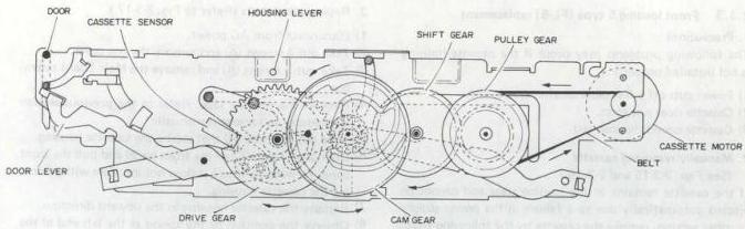
Fig. 2-3-13 Cassette housing - 3
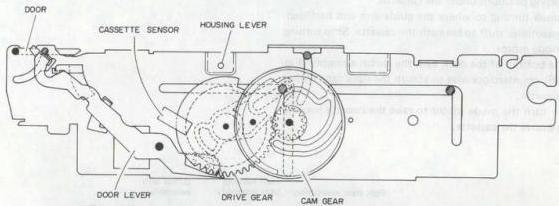
Fig. 2-3-14 Cassette housing - 4
2.3.3 Front loading 5 type (FL-5) replacement
1. Precautions
The following problems may occur if the cassette housing is not installed properly.
1) Power cuts off a few seconds after power ON. 2) Cassette does not eject. 3) Cassette cannot be inserted.
2. Manually removing cassette
(See Figs. 2-3-15 and 2-3-16.)
If the cassette remains in the loading state and cannot be ejected automatically due to a failure in the power supply or other section, remove the cassette by the following steps.
1) Disconnect from AC power. 2) Turn the mode motor by hand for clockwise rotation of the control cam. The pole base assemblies return to their unloading positions under the cassette. 3) Continue turning to where the guide arm and half loading assemblies shift to beneath the cassette. Stop turning the mode motor. 4) At the bottom of the deck turn the clutch assembly (Fig. 2-3-16) counterclockwise to absorb the slack tape within the cassette. 5) Again turn the mode motor to raise the cassette housing and remove the cassette.
3. Replacement steps (Refer to Fig. 2-3-17.)
1) Disconnect from AC power. 2) Take out 4 screws ① and remove the top cover. 3) Take out 5 screws ② and remove the Main board assembly. 4) Remove the cassette tape. Refer to the previous section if necessary to remove it manually. 5) Take out 4 screws ③ that secure the cassette housing. 6) Disengage 3 tabs ④ of the front panel and pull the front panel forward to where it does not interfere with removing the cassette housing. 7) Remove the cassette housing in the upward direction. 8) Observe the position of the spring at the left end of the cassette door. At the center of the door, carefully bend the door outwards and remove it from the right end.
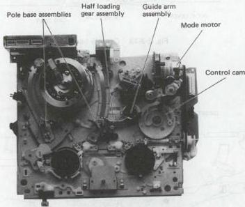
Fig. 2-3-15 Fig. 2-3-16
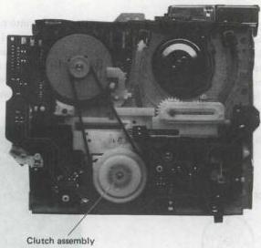
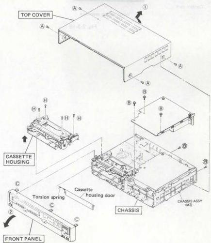
Fig. 2-3-17 Removal of external covers
- Housing installation (Refer to Figs. 2-3-18 and 2-3-19.)
1) On the main deck, observe the positional relationships of the parts indicated in Fig. 2-3-18. If necessary, turn the mode motor by hand to obtain these positions.
2) Refer to Fig. 2-3-19 and confirm that the clutch is engaged. If necessary, press the lever indicated by the arrow to where the clutch is locked.
3) Check that the new cassette housing is in the eject state (internal holder of the housing is locked in raised position).
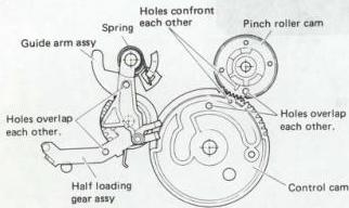
Fig. 2-3-18
4) Set the housing into place and secure with 4 screws.
5) Install the front panel and re-engage the tabs.
6) Supply power and use a spare cassette to check for normal loading and eject operations.
7) Disconnect from power, then reinstall the main board assembly and top cover.
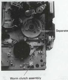
Fig. 2-3-19
2.3.4 Tray loading type status
1. Cassette housing
Two sensor switches detect the cassette housing status. One detects retraction of the cassette tray, while the other detects lowering and raising of the cassette.
Table 2-4-1 indicates the relationship between the cassette housing status and the sensor output.
| Cassette housing | Sensor output |
|---|---|
| During loading | H |
| Eject | H |
| Loading end | L |
| Eject | L |
| Cassette inserted |
Table 2-3-1
The sensor output is Low at both loading end and eject end. As which state cannot be determined immediately after power on, the start and end sensors are also polled. If one or both are Low, eject end is interpreted. If one or both are High, loading end is interpreted.
In view of the cassette housing control system, the following service points can be considered.
a) Insert and eject
After inserting a cassette, if loading is not completed within about 3 seconds, the cassette is ejected.
If eject is not completed within about 3 seconds, the cassette is loaded and the power cut off.
b) After inserting a cassette, the start and end sensor operations are as indicated in Table 2-4-2.
c) If backup has expired, at power on, the start and end sensors switch on and tape presence is detected.
| Start Sensor | End Sensor | Operation |
|---|---|---|
| Off | Off | Cassette loading end (Stop mode) |
| Off | On | Trailer tape detect |
| On | Off | Leader tape detect |
| On | On | Eject |
- Tape forwarded to start sensor off position.
Table 2-3-2
2. Cassette insertion and removal
The normal mode is described (i.e., timer mode, etc. is omitted).
1) Cassette absent
(1) Open/Close button
Extension and retraction of the cassette tray are enabled in both power on and off states. However, if the power was initially off, it remains on after the tray retracts.
(2) Play key
In the power on state, pressing the Play key extends the cassette tray.
2) Cassette tray extended
(1) Open/Close button
The tray retracts and the Eject mode is entered. Power remains on.
(2) Power button
The tray retracts and the Eject mode is entered. Power switches off.
3) Cassette (record enabled) set on tray
- If erase protector tab is absent, the Play mode is entered.
(1) Open/Close button
The tray retracts and the Stop mode is entered. Power remains on.
(2) Power button
The tray retracts and the Stop mode is entered. Power switches off.
(3) Play key
The tray retracts and the Play mode is entered.
(4) Tray pressed by hand (only full size cassette is lowered)
The tray retracts and the Stop mode is entered. Power remains on.
4) Tray retracted
(1) Open/Close button
Tray is extended, regardless of power on or off.
Notes
a) These operations are controlled by the syscon CPU.
b) Tray position is detected by the tray switch.
c) Cassette presence is detected by the 3 cassette switches, and start and end sensors.